
BIFFI GIG User manual

Installation, Operation and Maintenance Manual
MAN 601 Rev. 7
December 2020
Bif GIG
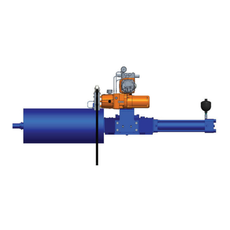
Double-Acting Direct Gas Actuator
Copyright © Bif. The information in this document is subject to change without notice. Updated data sheets can be obtained from our website www.bif.it or from your nearest Bif Center:
Bif Italia s.r.l. - Strada Bif 165, 29017 Fiorenzuola d'Arda (PC) – Italy PH: +39 0523 944 411 – bif_italia@bif.it

Revision Details
December 2020
Installation, Operation and Maintenance Manual
MAN 601 Rev. 7
Revision Details
Revision Details
Revision Date Description Prepared Checked Approved
7 December 2020 Migration to new template
6 April 2018 Updated Data-plate Ermanni Oreci Vigliano
5April 2016 Updated applicable regulation (chapter 1.1.1) Ermanni Oreci Vigliano
4 August 2015 Updated chapters 3.3.3 and 3.3.4 Ermanni Oreci Vigliano
3February 2013 Updated chapter 5.1.1 Ermanni Oreci Vigliano
2 July 2012 General update Ermanni Stoto Vigliano
1March 2009 General update Ermanni Stoto Vigliano
0May 1999 Document release Lazzarini Aliani Ziveri

i
Installation, Operation and Maintenance Manual
MAN 601 Rev. 7
Table of Contents
December 2020
Table of Contents
Section 1: General Warnings
1.1 Generalities................................................................................................... 1
1.1.1 Applicable Regulation ........................................................................ 1
1.1.2 Terms and Conditions......................................................................... 2
1.2 Identication Plate ........................................................................................ 2
1.3 Introducing the Actuator............................................................................... 3
1.4 Data Sheet .................................................................................................... 3
Section 2: Installation
2.1 Checks upon Actuator Receipt ...................................................................... 4
2.2 Actuator Handling......................................................................................... 4
2.3 Storage ......................................................................................................... 6
2.4 Actuator Assembly on the Valve.................................................................... 7
2.4.1 Types of Assembly.............................................................................. 7
2.4.2 Assembly Procedure......................................................................... 12
2.5 Pneumatic Connections .............................................................................. 13
2.6 Electrical Connections (If Any)..................................................................... 14
2.7 Commissioning........................................................................................... 15
Section 3: Operation and Use
3.1 Operation Description................................................................................. 16
3.2 Residual Risks.............................................................................................. 20
3.3 Operations.................................................................................................. 20
3.3.1 Local Pneumatic Operation .............................................................. 20
3.3.2 Electric Remote Control to Open and to Close .................................. 21
3.3.3 Emergency Manual Operation by MSJ / MHW ................................... 21
3.3.4 Emergency Manual Operation by MHP ............................................. 23
3.4 Calibration of the Angular Stroke ................................................................ 26
3.5 Calibration of Micro-switches (If Foreseen).................................................. 31
3.6 Calibration of the Operation Time............................................................... 32
Table of Contents

ii
Table of Contents
December 2020
Installation, Operation and Maintenance Manual
MAN 601 Rev. 7
Section 4: Operational Tests and Inspections
Operational Tests and Inspections..........................................................................34
Section 5: Maintenance
5.1 Periodic Maintenance.................................................................................. 35
5.1.1 Check and Restore Oil Level in the Hydraulic Manual Override .......... 36
5.2 Extraordinary Maintenance ......................................................................... 39
5.2.1 Replacement of Cylinder Seals .......................................................... 39
5.3 Dismantling and Demolition ....................................................................... 43
5.4 Lubrication of Mechanism........................................................................... 44
Section 6: Troubleshooting
6.1 Failure or Breakdown Research.................................................................... 45
Section 7: Layouts
7.1 Spare Parts Order........................................................................................ 46
7.2 Parts List for Maintenance and Replacing Procedure.................................... 47
Section 8: Date Report for Maintenance Operations
Date Report for Maintenance Operations...............................................................54
Table of Contents

Installation, Operation and Maintenance Manual
MAN 601 Rev. 7 December 2020
General Warnings 1
Section 1: General Warnings
Section 1: General Warnings
NOTICE
The manual is an integral part of the machine, it should be carefully read before carrying
out any operation and it should be kept for future references.
1.1 Generalities
Bif Italia s.r.l. actuators are conceived, manufactured and controlled according to the Quality
Control System in compliance with EN ISO 9001 international regulation.
1.1.1 Applicable Regulation
EN ISO 12100:2010: Safety of machinery – General principles for design –
Risk assessment and risk reduction
2006/42/EC: Machine directive
2014/68/EU: Directive for pressure PED equipment
2014/35/EU: Directive for low voltage equipment
2014/30/EU: Directive for the electromagnetic compatibility
2014/34/EU: Directive and safety instructions for use in hazardous area
NOTICE
Bif Italia s.r.l. pays the highest attention to collecting and verifying the documentation
contained in this user manual. However Bif Italia s.r.l. is not liable for any mistakes
contained in this manual, for damage or accidents due to the use of the latter. The
information contained is of exclusive reserved ownership of Bif Italia s.r.l. and may be
modied without prior notice. All rights reserved.

December 2020
Installation, Operation and Maintenance Manual
MAN 601 Rev. 7
General Warnings2
Section 1: General Warnings
1.1.2 Terms and Conditions
Bif Italia s.r.l. guarantees that all the items produced are free of defects in workmanship
and manufacturing materials and meet relevant current specications, provided they
are installed, used and serviced according to the instructions contained in the present
manual. The warranty can last either one year from the date of installation by the initial
user of the product, or eighteen months from the date of shipment to the initial user,
depending on which event occurs rst. All detailed warranty conditions are specied in the
documentation forwarded together with the product. This warranty does not cover special
products or components not warranted by subcontractors, or materials that were used or
installed improperly or were modied or repaired by unauthorized staff. In the event that
a fault condition be caused by improper installation, maintenance or use, or by irregular
working conditions, the repairs will be charged according to applicable fees.
The warranty and Bif Italia s.r.l. liability shall lapse in the event that any modication
or tampering whatsoever be performed on the actuator.
1.2 Identication Plate
! WARNING
It is forbidden to modify the information and the marks without previous written
authorization by Bif Italia s.r.l.
The plate fastened on the actuator contains the following information (Figure1).
Figure 1 Data plate

Installation, Operation and Maintenance Manual
MAN 601 Rev. 7 December 2020
General Warnings 3
Section 1: General Warnings
1.3 Introducing the Actuator
The direct gas actuator GIG was engineered and is manufactured to provide fail safe
operation for any quarter turn application such as ball, plug, buttery valves or dampers,
in both ON-OFF and Modulating heavy duty service.
The actuator (see Figure 2) is made up of a weatherproof scotch yoke mechanism
transforming the linear movement of the pneumatic cylinder (on closing or opening) into
the rotary movement, which is necessary for operation. The angular stroke of the yoke is
adjustable between 82° and 98° by means of the external mechanical stops screwed into
the left wall of the mechanism housing and into the end ange of the pneumatic cylinder.
The cover of the scotch yoke mechanism is arranged for the assembly of the required
accessories (positioner, signalling limit switches, position transducer, etc.) by means of
proper matching units. The above mentioned accessories are operated by the actuator
drive sleeve. The housing of the scotch yoke mechanism has a ange with threaded holes
to x the actuator to the valve either directly or, if required, with the interposition of an
adaptor ange or a mounting bracket. The actuator yoke has a hole with keyways suitable
for the assembly of an insert bush the internal hole of which is machined (by Bif or at
Customer's care), according to the shape and dimensions of the valve stem. Bif can supply
different types of control system following Customer's requirements.
The expected lifetime of actuator is approximately 25 years .
Supply uid Sweet, dry natural gas; sour high pressure gas; nitrogen or
instrument air
Operating temperature Standard: from –30 °C to +100 °C
Optional: from –60 °C to +140 °C
Supply pressure Please refer to technical document: “actuator data-sheet”
Figure 2 Identication of actuator parts
Manual handpump
MHP (optional)
Pneumatic cylinder
Valve position indicator
Valve Coupling
Scotch yoke
mechanism
1.4 Data Sheet
Hydraulic Cylinder
for GIG-MHP models or
second pneumatic cylinder
for “twin gas cylinder”
models (optional)

December 2020
Installation, Operation and Maintenance Manual
MAN 601 Rev. 7
Installation
4
Section 2: Installation
Section 2: Installation
2.1 Checks upon Actuator Receipt
• Check that the model, the serial number of the actuator and the technical data
reported on the identication plate correspond with those of order conrmation,
see Section 1.2.
• Check that the actuator is equipped with the ttings as provided for by
order conrmation.
• Check that the actuator was not damaged during transportation: if necessary,
renovate the painting according to the specication reported on the
order conrmation.
• If the actuator is received already assembled with the valve, its settings have
already been made at the factory.
• If the actuator is delivered separately from the valve, it is necessary to check,
and if required, to adjust the settings of the mechanical stops (Section 3.4) and of
micro-switches (if any) (Section 3.5).
2.2 Actuator Handling
NOTICE
The lifting and handling of the actuator must be done by qualied personnel and in
accordance with the laws and regulations in force. Avoid the lifted actuator to be hung
above the personnel.
! WARNING
The actuator must be lifted by means of a suitable lifting apparatus. The weight of the
actuators is indicated in the technical documentation attached to the equipment itself.
For lifting and moving the actuator, use only hooks tted with safety latch, like the one,
for example, shown in Figure 3.
Figure 3 Example of hook with safety latch

Installation, Operation and Maintenance Manual
MAN 601 Rev. 7 December 2020
Installation 5
Section 2: Installation
Figure 4 Lifting points for GIG / GIG-MHP / GIG-MSJ / GIG-MHW actuators
1-2 = Lifting points (obligatory)
3= Balancing point
! WARNING
3 = don’t lay the actuator on tie rods of cylinder/s and don’t lay the actuator on accessories
(manual handpump, manual jackscrew, pneumatic control group etc.).
• For lifting unbalanced loads, use ropes of different lengths or chains with
adjustable length.
• Check each time the conditions of all lifting equipment used and discard it if
not in perfect working order.
• Do not knot or twist the ropes so as not to reduce the lifting capacity or
produce torsional effects on the load being lifted.
• Use the utmost caution and remain at a safe distance from lifted actuator
unless absolutely necessary; do not stand or pass under suspended loads.
• Pay attention in putting under tension the ropes to prevent the load shifting
sideways in an uncontrolled manner.
• Use slings of such length that the angles of the leg from vertical are as narrow
as possible (αMAX < 20°).
• During handling, do not transport the suspended actuator above staff
members in charge of the operation.
! WARNING
Do not use the lifting eyelets on actuator to lift valve + actuator assembly.
1= point of support
2= supports for lateral positioning

December 2020
Installation, Operation and Maintenance Manual
MAN 601 Rev. 7
Installation
6
Section 2: Installation
2.3 Storage
If the actuator needs storage, before installation follow these steps:
• Place it on a wood surface in order not to deteriorate the area of valve coupling.
• Make sure that plastic plugs are present on the pneumatic and electrical
connections (if present).
• Check that the cover of the control group and of the limit switch box (if any) are
properly closed.
If the storage is long-term or outdoor:
• Keep the actuator protected from direct weather conditions.
• Replace plastic plugs of pneumatic and electrical connections (if any) with metal
plugs that guarantee perfect tightness.
• Coat with oil, grease or protection disc, the valve coupling area.
• Periodically operate the actuator (Section 3.3).
Figure 5
LIFTING LUGS TO BE USED FOR THE
ACTUATOR ONLY. DO NOT LIFT VALVE
AND ACTUATOR TOGETHER
DO NOT DISASSEMBLE TOP OR
BOTTOM COVER.
SPRING LOADED.
POTENTIAL ELECTROSTATIC CHARGE HAZARD
BIFFI IS NOT LIABLE FOR ANY
PERSONNEL INJURY DUE TO
INCORRECT USE
REFER TO IOM
This manual suits for next models
3
Table of contents
Other BIFFI Controllers manuals

BIFFI
BIFFI COMPACT Series User manual

BIFFI
BIFFI PLA User manual

BIFFI
BIFFI F02 Manual

BIFFI
BIFFI HLAS User manual

BIFFI
BIFFI HLAS-C Series User manual

BIFFI
BIFFI RPHD User manual

BIFFI
BIFFI GPO-EAC User manual

BIFFI
BIFFI ALGA-EAC Series User manual

BIFFI
BIFFI ALGAS-MHW User manual

BIFFI
BIFFI HLA User manual




Popular Controllers manuals by other brands

Digiplex
Digiplex DGP-848 Programming guide

YASKAWA
YASKAWA SGM series user manual

Sinope
Sinope Calypso RM3500ZB installation guide

Isimet
Isimet DLA Series Style 2 Installation, Operations, Start-up and Maintenance Instructions

LSIS
LSIS sv-ip5a user manual

Rockwell Automation
Rockwell Automation 1769-L31 installation instructions


