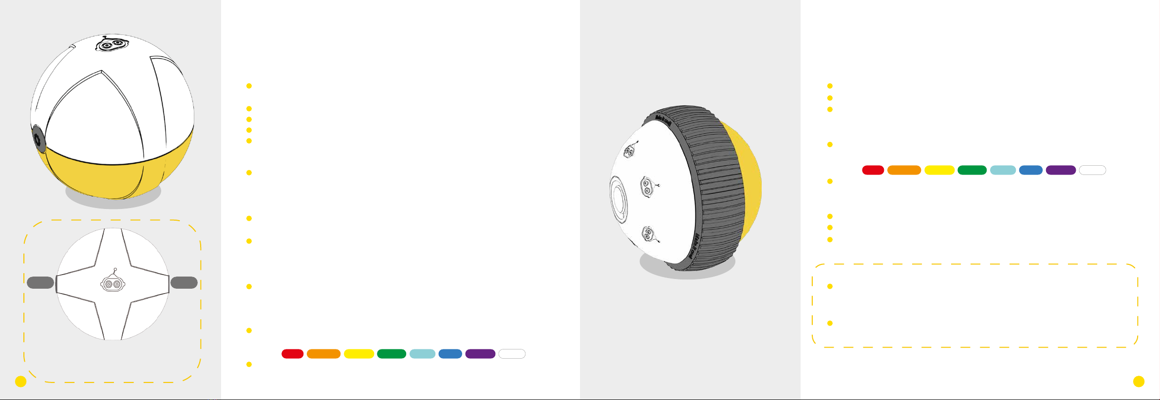
bellrobot Mabot User manual


Welcome to the world of Mabot!
Warning: “This product contains a small ball which may present a choking hazard.
Not suitable for children under 3 years.”
This specification covers the functions of all modules of the Mabot robot products,
not the list of packages that consumers buy.

Drive Ball
• It can display different color light;
• It can rotate clockwise and counter-clockwise;
• Each drive ball has one connector.
Indicator light instruction:
• The white cover of the drive ball is the lampshade. The default
color of the lampshade is white and and it can indicate eight
colors:
• Light modes: on, gradual pulsing, flashing, and off.
Operation parameters:
• Load-free rotate speed: 255rpm;
• Stalling torque: 1.2kg.cm;
• Load limit: 0.9 kg.
Attention:
· When the drive ball is loaded over its weight limit, it may
lead to abnormal rotation. Unloading is needed for proper
functioning or the ball will be damaged.
· No foreign matter should be placed between two balls to
impede rotation.
Control Ball
• It has modules for Bluetooth connection and a three-bracket
gyroscope;
• The Micro-USB port is for firmware upgrades only;
• It can display the status of the device;
• It can display different color lights;
• Each control ball has only one port.
Working Status:
• To start the system: Lampshade flashes once to show that it has
entered breathing mode (transform from a bright state to a dark
state), simultaneously chiming the tones for ‘Do Mi’ from the
buzzer;
• When the bluetooth is connected successfully: the lampshade
flashes twice, chiming “Do Re Me” from the buzzer;
• Downloading official programs: After successfully downloading,
the lampshade will flash green three times, playing a ‘Do Mi’
progression from the buzzer; if downloading fails, the lampshade
will flash red three times;
• Ready for self-balancing: the lampshade will flash blue three times
playing ‘Ti Ti’from the buzzer.
Light instructions:
• The white shade of the control ball is the lampshade. The default
color of the lampshade is white and and it can indicate 8 different
colors:
• Light activity: on, gradual pulse, flashing, and off.
Operating Instruction:
There are two buttons on the control ball; button 1
and button 2 share the same function: they can both
start or stop Mabot GO or other built-in programs
from the Mabot IDE coding card.;
button 1 button 2
The operating hub of Mabot for controlling performance of
other electronic components.
1 21
The module that can move on flat surfaces.
Red Orange Yellow Green Cyan Blue Purple White

Battery Ball
The power supply module of Mabot.
• The micro-USB supports a device charging function;
• Battery indicator lights on both sides of the charging port;
• Every battery ball has four ports, on each side of the ball.
Battery parameters:
• Typical capacity: 640mAh;
• Standard voltage: 7.4V;
• Recommended charge temperature: room temperature
Instruction to the switch:
• When the Mabot is off, press and hold the power-on button for 2
second to boot up; the indicator light of the battery ball will turn
on;
• When the Mabot is on, press and hold the button for 3 seconds
to shut it down; the indicator light of the battery ball will turn off.
Instructions for the indicator lights of the battery ball:
• When the light is green, it means that the battery ball is near full
charge;
• When a red indicator light appears, it means that the battery is
low;
• When the battery ball is low on power, certain modules of the
Mabot may become unresponsive;
• The battery ball will show a blue light while charging. A green
light means it is fully charged.
Attention:
· Never use a damaged battery ball;
· Never insert any sharp metal into the connectors, as it may
cause short circuiting or permanent damage;
· Keep the battery ball off when not in use. Please charge and
check the battery ball every fourth months to keep in working
condition.
· Please use under adult supervision. Remove the charger
immediately after charging has completed.
· The battery ball can be turned on while charging. Shutting
the device down before charging is suggested for extended
times.
Charge and general instructions:
• Service time — the more power-hungry devices connected to a
single battery ball (such as rotate joint ball, swing joint ball, drive
ball), the shorter amount of time it will operate.
(e.g. When the Mabot starter robot runs continuously at its
highest rate with the control ball and drive ball lights on, the
battery ball can continue working for around 50 minutes.)
• Charging time—It usually takes two hours to fully charge. The
time spent varies based on power adapter standards (5V and 1A
power adapters are recommended).
Charging
High power
Low power
Switch on / turn off power by switch
43

Color Sensor
It can detect the color and intensity of light.
• Colors options:
• Levels of light: 0 (extremely dark) to 100 (extremely bright);
• Detection angle: the lamp head is perpendicular to the object
• Detection distance: 1 cm;
• Each color sensing ball has one port.
Mode instructions: Three status of color sensing ball:
• Color mode: When lamp base is white, it catches the color detected by the color
sensing ball sensor.
• Reflected light intensity mode: When lamp base turns red ,it measures reflected
light’s intensity from the objects exposed to it;
• Environmental light intensity mode: When lamp base turns off, it can measure the
light intensity of environmental light through the sensor.
• When in color mode or reflected light intensity mode, make sure the color sensing
ball is at a right angle and is not touching the surface of the object being detected
(e.g.: a line-tracking robot from the package).
Attention:
· Please do not smear or paste things onto the lamp or it will
compromise the detector’s sensitivity.
· Mirror and dark colored objects will compromise the detec-
tor’s normal status.
· The parameters above are for reference only. Do not stare at
the lamp for extended periods.
It can detect if there is any obstacle ahead.
• Angle of detection: The lamp head and object are perpendicu-
lar.
• It can measure distances using infrared light, measuring
between 5~15cm (the parameter is based in the test results done
on a white A4 piece of paper);
• Each infrared sensing ball has one input.
Attention:
· Please do not smear or paste things onto the black cover or
it will compromise the detector’s sensitivity.
· Mirror and dark colored objects will compromise the detec-
tor’s ability to operate.
· The parameters are for reference only.
Infrared Sensor
5-15cm
Color Mode
Reflective light
mode
Environmental light
mode
65
Red Orange Yellow Green Blue Purple White Black

normal state
pressed
Touch Sensor
It can check whether the red button of the touch sensing ball is
under pressure.
•It can detect if the red button of the touch sensing ball is under
pressure.
• The indicator light is above the touch button;
• The touch button does not transmit signals or electrical
current.
• Every color sensing ball has four ports, on each side of the ball.
Instructions:
• When the button is pressed past 2.2mm, the light will flash
green.
• Pressure on the button should not be more than 1kg.
Attention:
Manually damaging or pulling the button by force is strictly
prohibited.
Every 6-port connection ball has 6 connections, each at a 90°
angle.
Every 3-port connection ball has 3 connectors, each at a 120°
angle.
3-Port Connection Ball
3-port connection ball is used for connecting other module
balls, to secure the structure, to connect electrical current,
and to transmit signals.
6-Port Connection Ball
6-port connection ball is used to connect other balls, to
secure the structure, to connect electrical currents, and to
transmit signals.
87
The light is green and flickering when the displacement
is 2.2mm from the initial position.

Rotating Joint
It can rotate objects horizontally.
• The rotary angle is ±75°;
• Load torque: 0.55 kg.cm;
• Load limit: 0.55kg;
• Every rotate joint ball has
two connection points.
Attention:
Don’t break off the module with hands when it is energized,
or it will damage the module. the loaded object is restricted
by weight. If the loaded object cannot rotate normally, the
object should be taken down immediately, or it might be
damaged. No foreign matter obstructs the rotation between
the two hemispheres.
Swinging Joint
This module can swing objects to left and right.
• Can swing approximately 75°;
• Load torque: 0.55 kg/cm;
• Load limit: 0.32kg;
• Each swing joint ball has
two connections.
Attention:
Don’t break off the module with hands when it is energized,
or it will damage the module. the loaded object is restricted
by weight. If the loaded object cannot rotate normally, the
object should be taken down immediately, or it might be
damaged. No foreign matter obstructs the rotation between
the two hemispheres.
75° 75°
Rotation Angle±75°
109

Small Connector
Small connector is used to connect all the module balls, to
secure the structure, to connect electrical current, and to trans-
mit signals.
Structural Connector
Structural connector is used to connect all the module balls, to
secure structures, but not to connect electrical current or to
transmit signals.
Medium Connector
Medium rod connector is used to connect all the module
balls, to secure structure, to connect electrical current, to
transmit signals, and to enrich the Mabot’s functionality.
Long Connector
Length: three unit lengths of one port .
1211
Length: equal length to one
battery ball.

5-Hole Beam
5-hole beam is used to secure structure, decorate and develop.
• It can connect at the angle of 45° or 90°.
• It has 5 connectors.
9-Hole Beam
9-hole beam is used to secure structure, decorate and develop.
• It can connect at the angle of 45° or 90°.
• It has 9 connectors.
Data Cord
Communication cord is for signal transmission between modules only, not for electric current trans-
mission.
How to use it: When a majority modules are power-consuming (such as rotate joint ball, swing joint ball,
drive ball) in the Mabot, the exported electric current from one single battery ball may not meet the power
requirement, so one needs to group power-consuming modules with different battery balls for respective
power supply. The communication cord can transmit commanding signals between multiple battery packs.
Power Cord
Power cord is for transmission of both electrical current and signal.
1413

Wheel Plug
Wheel plug is for structure supporting or resistance decrease
( it is used as a driven roller).
Rubber Plug
Rubber plug is for structure supporting or resistance decrease
( it is used as the robot’s foot).
Lego Adapter B
The adapter of LEGO nano-blocks.
Lego Adapter A
The adapter of LEGO package & EV3 package.
1615
Table of contents


