
BCF Solutions DOG 2 PTZ User manual

DPTZ-Kit-1/2-v1_manual-v2.2
DIGITAL OBSERVATION GUARD
HIGH PERFORMANCE LOW
PROFILE PTZ KIT USER MANUAL
Version 2.2
May 17, 2013

1
Table of Contents
High Performance Low Profile PTZ Kit Description................................................................................... 3
High Performance Low Profile PTZ Unit Basic Operation.......................................................................... 4
Mounting the High Performance Low Profile PTZ Units............................................................................ 5
Surface Mounting the High Performance Low Profile PTZ Unit ............................................................ 5
Wall or Pole Mounting the Pan-Tilt Unit................................................................................................. 7
Connecting the Camera to the Pan Tilt Unit............................................................................................... 10
Terminating and connecting the CAT-5 Cable........................................................................................... 12
Connecting the Thermal Camera and IR Illuminator ................................................................................. 15
Connecting the DOG IR Illuminator ...................................................................................................... 16
Connecting the IR Illuminator Cable.................................................................................................. 16
Connecting the Thermal Camera............................................................................................................ 17
Connecting PTZ Units to the Base Station................................................................................................. 18
Troubleshooting.......................................................................................................................................... 20
Contact Info/Tech Support ......................................................................................................................... 21
Replacement Parts ...................................................................................................................................... 21

2
Table of Figures
Figure 1: High Performance Low Profile PTZ Kit with Optional Military Grade Case.............................. 3
Figure 2: High Performance Low Profile PTZ Kit Identification Label...................................................... 3
Figure 3: High Performance Low Profile PTZ Unit Channel ID Number.................................................. 4
Figure 4: Surface Mount accessories............................................................................................................ 5
Figure 5: Attaching the Pedestal Mount Adapter Plate to the High Performance Low Profile PTZ ........... 6
Figure 6: Mounting the Pedestal onto a Surface........................................................................................... 7
Figure 7: Attaching the Bracket to a Wall or Vertical Surface..................................................................... 8
Figure 8: Attaching the Bracket to a Pole..................................................................................................... 8
Figure 9: Attach Pan Tilt Unit to the Bracket............................................................................................... 9
Figure 10: Camera Tube Mounting Hardware............................................................................................ 10
Figure 11: Attaching Camera Tube to Pan Tilt Unit .................................................................................. 10
Figure 12: Attaching Camera Tube Cable to Pan Tilt Unit........................................................................ 11
Figure 13: Attaching CAT-5 Cable to Pan Tilt Unit .................................................................................. 11
Figure 14: Assembled Pan Tilt Unit with Camera Tube ............................................................................ 12
Figure 15: Weatherproof Connector Parts.................................................................................................. 12
Figure 16: CAT-5 cable termination and connection ................................................................................. 13
Figure 17: Strain Relief of the Cable.......................................................................................................... 14
Figure 18: Camera Adapter Accessories .................................................................................................... 15
Figure 19: IR Illuminator/Thermal Camera Adapter Plate attachment ...................................................... 15
Figure 20: Installing an IR Illuminator....................................................................................................... 16
Figure 21: Connecting the IR Illuminator Power Cable............................................................................. 16
Figure 22: Attaching a Thermal Camera.................................................................................................... 17
Figure 23: Connecting the Thermal Camera Cable to the High Performance Low Profile PTZ .............. 18
Figure 24: High Performance Low Profile PTZ Unit Connection Diagram ............................................. 19
3
High Performance Low Profile PTZ Kit Description
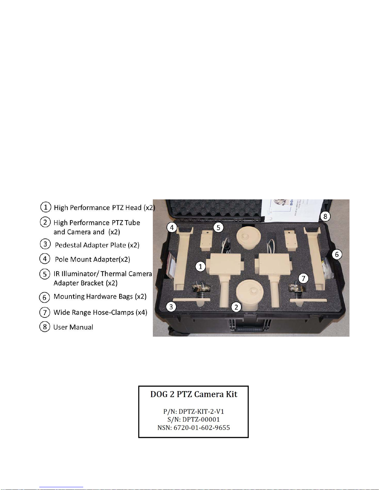
The High Performance Low Profile PTZ kit is an accessory kit for installation on the DOG Base Kit.
Each High Performance Low Profile PTZ case contains 2 High Performance Low Profile PTZ units with
attached zoom cameras, and associated accessories. The High Performance Low Profile PTZ units are
capable of providing 360 degrees of horizontal (pan) motion and 180 degrees (+/- 90◦) of vertical (tilt)
motion. The units can be either wall-mounted or pole-mounted using the Wall Mount Brackets and Pole
Mount Adapters provided in the kit. The units are also surface mountable using the Pedestal Mount
Adapter Plates, also provided in the kit. The IR Illuminator/Thermal Camera Adapter Plates allow an IR
Illuminator or Thermal Camera to be mounted if needed. This allows the IR illuminator beam (or
Thermal Camera image) to track with the PTZ Camera as the High Performance Low Profile PTZ head
moves. Each High Performance Low Profile PTZ unit is assigned a Channel ID reference number from
1 to 8 (1-4 for 4 channel DOG systems) for identification purposes. An example of a High Performance
Low Profile PTZ Kit is shown in the figure below.
**WHEN RE-PACKING THE KIT, PRIOR TO POWER-DOWN, USE THE DVR DOME
CONTROLS TO POSITION THE TILT AXIS AT 0-DEGREES VERTICAL OR THE UNIT
WILL NOT FIT**
Figure 1: High Performance Low Profile PTZ Kit with Optional Military Grade Case
Each case can be identified by a decal just above the handle as shown in the figure below. The “DPTZ”
stands for DOG Pan-Tilt-Zoom and is followed by the kit serial number.
Figure 2: High Performance Low Profile PTZ Kit Identification Label

4
High Performance Low Profile PTZ Unit Basic Operation
Each High Performance Low Profile PTZ unit draws its power and data commands from, and transmits
its video to, the Base Station. The High Performance Low Profile PTZ unit can be placed up to 500m
from the DOG Base Station, using CAT-5 cable with no external power source required. The High
Performance Low Profile PTZ Channel ID number (1-8 for 8 channel systems and 1-4 for 4 channel
systems) is indicated by a decal on the bottom of the unit as seen in the figure below and must be
connected to the corresponding channel on the Base Station. * Make sure to keep track of the channel
number of each High Performance Low Profile PTZ unit.
Figure 3: High Performance Low Profile PTZ Unit Channel ID Number
To operate the High Performance Low Profile PTZ unit, the user simply selects the channel of the camera
from the buttons on the front of the Base Station DVR and then pushes the Dome button on the DVR.
This brings up an on-screen message which indicates that the pan-tilt arrow buttons on the DVR are
active. At this point, pushing the arrow buttons moves the camera as indicated by the arrow buttons.
Details of the High Performance Low Profile PTZ unit setup are provided in the following sections.

5
Mounting the High Performance Low Profile PTZ Units
The two main mounting methods of surface mounting and wall/pole mounting are covered in the
following sections.
Surface Mounting the High Performance Low Profile PTZ Unit
Surface mounting the High Performance Low Profile PTZ unit to a flat surface such as a roof or pedestal
requires the attachment of a Pedestal Mount Adapter Plate using the bag of the included Pedestal Mount
screws as seen in the figure below. The camera Home or 0 Position indicated in the figure is the 0 degree
pan position and should be pointed at the center of the surveillance area. The camera will pan +/- 180
degrees about that point. The Alignment Hole indicated in the figure is for alignment of the pan tilt unit
shaft.
Figure 4: Surface Mount accessories
Position the adapter plate, with the non-countersunk-holes against the shaft (countersunk holes on other
side of the shaft) and align the pin on the shaft with the Alignment hole on the plate as seen in the figure
below. Insert the three 1/4-20 x 5/8 flathead machine screws and tighten the screws using a Phillips head
screwdriver, but do not tighten the screws completely until all three are inserted.

6
Figure 5: Attaching the Pedestal Mount Adapter Plate to the High Performance Low Profile PTZ
The High Performance Low Profile PTZ camera has a Stop Zone at +/- 180 degrees where it has to
change directions in order to keep moving. The Stop Zone is on the exact opposite side of the shaft as the

7
Home or 0 Position as seen in the figure above. The camera should be mounted so that the Home or 0
Position is pointed at the area of interest and the Stop Zone is pointed away from the area of interest.
**Important: The Home or 0 Position hole should point to the center of the surveillance area to
avoid Stop Zone related horizontal (pan) movement delays.
For a rooftop mount, simply place the assembled unit on a piece of plywood or directly onto the roof,
then drive wood or sheet metal screws (#8 or smaller) through the four screw holes along the perimeter of
the Pedestal Mount Adapter Plate and into the mounting surface as shown in the figure below.
Figure 6: Mounting the Pedestal onto a Surface
Wall or Pole Mounting the Pan-Tilt Unit
The wall/pole mounting bracket provided in the kit is used for attaching to a vertical surface like a wall or
pole. It is recommended to mount the bracket to the vertical surface first, then mount the pan tilt unit and
the camera to the bracket, though this order is not necessary. To mount the bracket to a wall simply hold
the bracket on the desired location and drive wood or sheet metal screws through the four holes as seen in
the figure below.

8
Figure 7: Attaching the Bracket to a Wall or Vertical Surface
To attach the mounting bracket to a pole, place and hold the bracket in the desired location. Take one of
the provided steel fastener straps from the kit and wrap it around the bracket base so that the steel band
lines up with the notched grooves on the edges of the bracket as shown in the figure below. Tighten the
steel fastener strap with a flat head screwdriver as shown.
Figure 8: Attaching the Bracket to a Pole
Once the bracket has been securely connected to a wall or pole, pull on it to make sure that it will hold
the weight of the pan tilt unit and camera. Next remove the bolts from the Pole Mount Bracket bag
provided in the kits along with the supplied Allen wrench. Place the pan tilt unit on top of the bracket
and align the pin on the shaft with the alignment hole in the bracket as seen in the figure below. Then
place a lock washer on each bolt and insert the bolts into the holes from underneath the bracket as shown.
Screw the bolts down with the Allen wrench until tight as seen below.
*It is recommended that this operation be done by two people or more. *

9
Figure 9: Attach Pan Tilt Unit to the Bracket
Table of contents








