Bard W48A12 User manual

Manual 2100-515B
Page 1 of 23
INSTALLATION INSTRUCTIONS
WALL MOUNTED
PACKAGE AIR CONDITIONERS
MODELS
W48A12 W48L12
W60A12 W60L12
W48A13 W48L13
W60A13 W60L13
W70A13 W70L13
Manual : 2100-515B
Supersedes: 2100-515A
File: Volume III Tab 16
Date: 12-15-11
Bard Manufacturing Company, Inc.
Bryan, Ohio 43506
Since 1914...Moving ahead just as planned.

Manual 2100-515B
Page 2 of 23
Contents
Figures
Figure 1 Unit Dimensions...................................... 7
Figure 2 Unit Dimensions...................................... 8
Figure 3 Unit Dimensions...................................... 9
Figure 4 Unit Dimensions.................................... 10
Figure 5 Unit Dimensions.....................................11
Figure 6 Unit Dimensions.....................................11
Figure 7 Wall Mounting Instructions.................... 12
Figure 8 Wall Mounting Instructions.................... 13
Figure 9 Electric Heat Clearance ........................ 14
Figure 10 Wall Mounting Installations ................... 15
Figure 11 Wall Mounting Installations ................... 15
Figure 12 Common Wall Mounting Installations.... 16
Figure 13 Fan Blade Setting ................................. 21
Tables
Table 1 Maximum ESP Electric Heat Only.......... 6
Table 2 Fan Blade Dimensions.......................... 21
Table 3 Rated CFM & ESP ................................ 21
Table 4 Indoor Blower Performance .................. 21
Table 5 Cooling Pressure .................................. 22
Table 6 Electrical Specifications W**A/L ........... 22
Table 7 Optional Accessories ............................ 23
Table 8 Electric Heat ......................................... 23
Getting Other Information and Publications 3
Wall Mount General Information
Wall Mount Model Nomenclature ............................ 4
Shipping Damage .................................................... 4
General ................................................................ 4
Duct Work................................................................ 5
Condensate Drain.................................................... 5
Filters ................................................................ 5
Installation Instructions
Wall Mounting Information....................................... 6
Mounting the Unit .................................................... 6
Clearances Required............................................... 6
Wiring – Main Power ............................................. 17
Wiring – Low Voltage Wiring ................................. 17
Start Up — R-410A
General .............................................................. 18
Topping Off System Charge................................... 18
Safety Practices..................................................... 18
Important Installer Note ......................................... 19
High & Low Pressure Switch ................................. 19
Three Phase Scroll Compressor............................ 19
Phase Monitor ....................................................... 19
Condenser Fan Operation ..................................... 19
Service Hints ......................................................... 19
Sequence of Operation.......................................... 20
Compressor Control Module.................................. 20
Adjustments ........................................................... 20
Pressure Service Ports.......................................... 20
Troubleshooting
Fan Blade Setting Dimensions .............................. 21
Removal of Fan Shroud......................................... 21
Refrigerant Charge ................................................ 21

Manual 2100-515B
Page 3 of 23
GETTING OTHER INFORMATION AND PUBLICATIONS
These publications can help you install the air
conditioner or heat pump. You can usually find these at
your local library or purchase them directly from the
publisher. Be sure to consult current edition of each
standard.
National Electrical Code ...................... ANSI/NFPA 70
Standard for the Installation .............. ANSI/NFPA 90A
of Air Conditioning and Ventilating Systems
Standard for Warm Air ...................... ANSI/NFPA90B
Heating and Air Conditioning Systems
Load Calculation for ............................ACCA Manual J
Residential Winter and Summer Air Conditioning
Duct Design for Residential .............. ACCA Manual D
Winter and Summer Air Conditioning and Equipment
Selection
FOR MORE INFORMATION, CONTACT
THESE PUBLISHERS:
ACCA Air Conditioning Contractors of America
1712 New Hampshire Ave. N.W.
Washington, DC 20009
Telephone: (202) 483-9370
Fax: (202) 234-4721
ANSI American National Standards Institute
11 West Street, 13th Floor
New York, NY 10036
Telephone: (212) 642-4900
Fax: (212) 302-1286
ASHRAE American Society of Heating, Refrigeration
and Air Conditioning Engineers, Inc.
1791 Tullie Circle, N.E.
Atlanta, GA 30329-2305
Telephone: (404) 636-8400
Fax: (404) 321-5478
NFPA National Fire Protection Association
Batterymarch Park
P.O. Box 9101
Quincy, MA 02269-9901
Telephone: (800) 344-3555
Fax: (617) 984-7057

Manual 2100-515B
Page 4 of 23
WALL MOUNT GENERAL INFORMATION
AIR CONDITIONER WALL MOUNT MODEL NOMENCLATURE
W48 A 1 2 A 10 B X X X X A
NOTE: Vent option B is without exhaust capability. May require separate field supplied barometric relief in building.
SHIPPING DAMAGE
Upon receipt of equipment, the carton should be
checked for external signs of shipping damage. If
damage is found, the receiving party must contact the
last carrier immediately, preferably in writing,
requesting inspection by the carrier’s agent.
GENERAL
The equipment covered in this manual is to be installed
by trained, experienced service and installation
technicians.
The refrigerant system is completely assembled and
charged. All internal wiring is complete.
The unit is designed for use with or without duct work.
Flanges are provided for attaching the supply and return
ducts.
These instructions explain the recommended method to
install the air cooled self-contained unit and the
electrical wiring connections to the unit.
These instructions and any instructions packaged with
any separate equipment required to make up the entire
air conditioning system should be carefully read before
beginning the installation. Note particularly “Starting
Procedure” and any tags and/or labels attached to the
equipment.
While these instructions are intended as a general
recommended guide, they do not supersede any national
and/or local codes in any way. Authorities having
jurisdiction should be consulted before the installation is
made. See Page 3 for information on codes and
standards.
Size of unit for a proposed installation should be based
on heat loss calculation made according to methods of
Air Conditioning Contractors of America (ACCA). The
air duct should be installed in accordance with the
Standards of the National Fire Protection Association
for the Installation of Air Conditioning and Ventilating
Systems of Other Than Residence Type, NFPA No.
90A, and Residence Type Warm Air Heating and Air
Conditioning Systems, NFPA No. 90B. Where local
regulations are at a variance with instructions, installer
should adhere to local codes.
KW
MODELNUMBER CONTROLMODULES
(SeeSpec.SheetS3397)
VOLTS & PHASE
A - 230/208/60/1
REVISIONS
VENTILATIONOPTIONS
B - Blank-offPlate
FILTEROPTIONS
X - OneInchThrowaway(Standard)(W48A/L12&W60A/L12)
W - OneInchWashable(W48A/L12&W60A/L12)
P - TwoInchPleated(W48A/L12&W60A/L12)
N - NoFilter(W48A/L13&W60A/L13)
COLOROPTIONS
X - Beige(Standard)
1 - White
2 - MesaTan
4 - BuckeyeGray
5 - DesertBrown
8 - DarkBronze
A - Aluminum
S - StainlessSteel
COILOPTIONS
X - Standard
1 - PhenolicCoatedEvaporator
2 - PhenolicCoatedCondenser
3 - PhenolicCoatedEvaporator
andCondenser
OUTLETOPTIONS
X -Front(Standard)
CAPACITY
48 - 4Ton
60 - 5Ton
70 - 6Ton
A - AirConditioner
L - LeftHandAirConditioner
2- 2Ton AirOpeningson5 Ton Cabinet
3- 3 Ton Air Openings on5TonCabinet

Manual 2100-515B
Page 5 of 23
DUCT WORK
All duct work, supply and return, must be properly sized
for the design airflow requirement of the equipment.
Air Conditioning Contractors of America (ACCA) is an
excellent guide to proper sizing. All duct work or
portions thereof not in the conditioned space should be
properly insulated in order to both conserve energy and
prevent condensation or moisture damage.
Refer to Maximum ESP of operation Electric Heat
Table.
Design the duct work according to methods given by the
AirConditioning Contractors of America (ACCA).
When duct runs through unheated spaces, it should be
insulated with a minimum of one inch of insulation. Use
insulation with a vapor barrier on the outside of the
insulation. Flexible joints should be used to connect the
duct work to the equipment in order to keep the noise
transmissiontoaminimum.
For model series W48, W60 and W70, a 1/4 inch
clearance to combustible material for the first three feet
of duct attached to the outlet air frame is required. See
Wall Mounting Instructions and Figures for further
details.
Ducts through the walls must be insulated and all joints
taped or sealed to prevent air or moisture entering the
wallcavity.
Some installations may not require any return air duct. A
metallic return air grille is required with installations not
requiring a return air duct. The spacing between louvers
on the grille shall not be larger than 5/8 inch.
Any grille that meets with 5/8 inch louver criteria may be
used. It is recommended that Bard Return Air Grille Kit
RG2 through RG5 or RFG2 through RFG5 be installed
when no return duct is used. Contact distributor or
factory for ordering information. If using a return air
filter grille, filters must be of sufficient size to allow a
maximum velocity of 400 fpm.
NOTE: If no return air duct is used, applicable
installation codes may limit this cabinet to
installation only in a single story structure.
CONDENSATE DRAIN
A plastic drain hose extends from the drain pan at the
top of the unit down to the unit base. There are
openings in the unit base for the drain hose to pass
through. In the event the drain hose is connected to a
drain system of some type, it must be an open or vented
type system to assure proper drainage.
FILTERS
W48A12, W48L12 & W60A12, W60L12 ONLY
A 1-inch throw away filter is supplied with each unit.
The filter slides into position making it easy to service.
This filter can be serviced from the outside by removing
the service door. A 1-inch washable filter and a 2-inch
pleated filter are also available as optional accessories.
The internal filter brackets are adjustable to
accommodate the 2-inch filter by bending the metal tabs
holding the 1-inch filter down. There are two tabs on
each side of the filter.
NOTE: W48A13, W48L13, W60A13, W60L13 and
W70A13, W70L13 models require the use of a
return air filter grille.

Manual 2100-515B
Page 6 of 23
sseccAecivreSrofderiuqeRsecnaraelC wolfriAresnednoCetauqedAdna SLEDOM EDISTFEL EDISTHGIR
A07W,A06W,A84W "02 "02
L07W,L06W,L84W "02 "02
NOTE: For side by side installation of two (2) W**A models there
must be 20" between units. This can be reduced to 15" by using
a W**L model (left side compressor and controls) for the left unit
and WA (right side compressor and controls) for right unit.
See W**A Specification S3397 & W**L Specification S3400
and Specification Sheet S3409 for 6-Ton W**A / W**L.
INSTALLATION INSTRUCTIONS
WALL MOUNTING INFORMATION
1.
Two holes for the supply and return air openings must
be cut through the wall as shown in Figure 1 or 2.
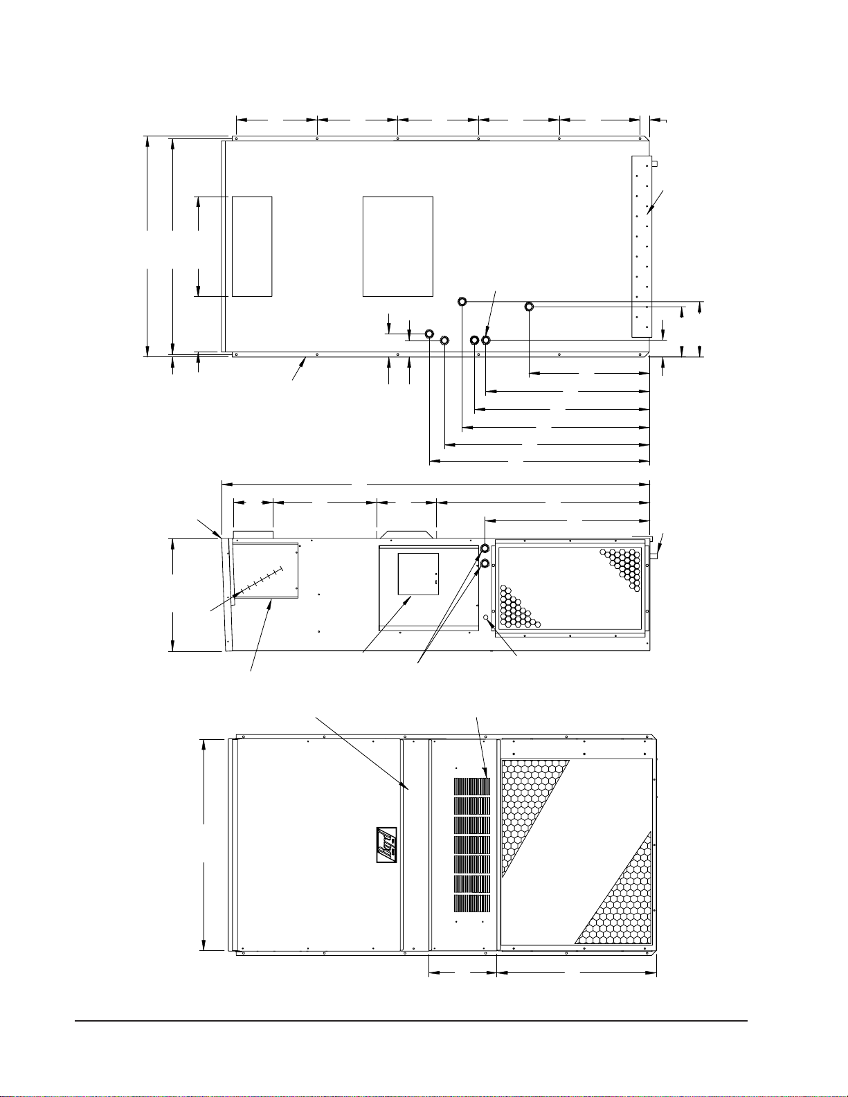
Figure 1 is for models W48A13 and W60A13.
Figure 2 is for models W48A12 and W60A13.
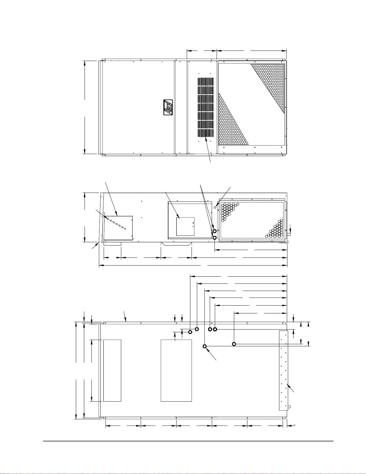
Figure 3 is for models W48L13 and W60L13.
Figure 4 is for models W48L12 and W60L12
Figure 5 is for model W70A13
Figure 6 is for model W70L13
2. On wood frame walls, the wall construction must be
strong and rigid enough to carry the weight of the
unit without transmitting any unit vibration.
3. Concrete block walls must be thoroughly inspected
to insure that they are capable of carrying the weight
of the installed unit.
W48A12, W48L12 & W60A12, W60L12 ONLY
These units are equipped with adjustable return and
supply air flanges. The flanges are adjustable side to side
in 1" increments. This allows these units to be adjusted
so that in side by side applications these units can replace
two 2 Ton units using the same wall openings.
MOUNTING THE UNIT
1. These units are secured by wall mounting brackets
which secure the unit to the outside wall surface at
both sides. A bottom mounting bracket is provided
for ease of installation, but is not required.
2.
The unit itself is suitable for 0 inch clearance, but the
supply air duct flange and the first 3 feet of supply air
duct require a minimum of 1/4 inch clearance to
combustible material. If a combustible wall use a
minimum of 30½" x 10½" dimensions for sizing.
However, it is generally recommended that a 1 inch
clearance is used for ease of installation and maintaining
the required clearance to combustible material. The
supply air opening would then be 32" x 12".
3. Locate and mark lag bolt locations and bottom
mounting bracket location.
4. Mount bottom mounting bracket.
5.
Hook top rain flashing under back bend of top. Top rain
flashing is shipped secured to the right side of the back.
6.
Position unit in opening and secure with 5/16 lag bolts;
use 7/8 inch diameter flat washers on the lag bolts.
7. Secure rain flashing to wall and caulk across entire
length of top.
8. For additional mounting rigidity, the return air and
supply air frames or collars can be drilled and
screwed or welded to the structural wall itself
(depending upon wall construction). Be sure to
observe required clearance if combustible wall.
9. On side by side installations, maintain a minimum of
20 inches clearance on right side to allow access to
control panel and heat strips, and to allow proper
airflow to the outdoor coil. Additional clearance
may be required to meet local or national codes.
WARNING
Fire hazard can result if 1/4 inch clearance to
combustible materials for supply air duct is
not maintained.
WARNING
Failure to provide the 1/4 inch clearance
between the supply duct and a combustible
surface for the first 3 feet of duct can result in
fire causing damage, injury or death.
TABLE 1
MAXIMUM ESP OF OPERATION
ELECTRIC HEAT ONLY
SLEDOMPSE
-31A06W YLNO
-31L06W YLNO
-31A07W YLNO
-31L07W YLNO
50A 01A 01A 01A
4.3.3.3.
VALUES SHOWN ARE FOR UNITS EQUIPPED WITH
STANDARD 1" THROWAWAY FILTERS OR 1" WASHABLE
FILTERS. DERATE ESP BY .15 FOR 2" PLEATED FILTERS.

Manual 2100-515B
Page 7 of 23
1.88
16.00
16.00
16.00
16.00
16.00
43.88
43.00.44
27.88
23.87
32.50
34.75
37.13
40.63
43.63
7.88
18.00
13.88
43.00
32.69
84.88
42.00
13.50
31.50
7.06
22.25
3.31
4.56
10.0
11.0
3.25
Side Wall
Back View
Ventilation Air
Supply
Air Opening
Bracket
Installation
Return
Air Opening
Electric
Heat
Electrical
Drain
Built In Slope
Top 2° Pitch
Panel
(Built In)
Heater
Access
Circuit Breaker
Disconnect Access
Panel (Lockable)
Entrances
Mounting Brackets
Entrances
Condenser Airflow
is Blowthrough on
All Models
Front View
Low Voltage
Right Side View
Electrical
Bottom
Electrical
Entrances
MIS-2610
FIGURE 1
UNITDIMENSIONS
W48A13 & W60A13

Manual 2100-515B
Page 8 of 23
11.0
16.00
16.00
16.00
16.00
16.00
43.88
.44
3.25
19.88
23.87
32.50
34.75
37.13
40.63
43.63
7.88
20.50
11.88
42.25
32.69
84.88
42.00
13.50
31.50
1.88
From 11.0" to
3.31
22.25
4.56
10.0
6.5" each side
Adjustable
43.00
Back View
Filter Access
Side Wall
Mounting Brackets
Air Opening
Supply
Installation
Bracket
Ventilation Air
Air Opening
Return
(Built In)
Heat
Electric
Drain
Right Side View
Top 2° Pitch
Built In Slope
Panel
Access
Heater
Panel (Lockable)
Disconnect Access
Circuit Breaker
Entrances
Entrances
Electrical
All Models
is Blowthrough on
Front View
Low Voltage
Condenser Airflow
Door
Electrical
Bottom
Electrical
Entrances
MIS-2609
FIGURE 2
UNITDIMENSIONS
W48A12 & W60A12

Manual 2100-515B
Page 9 of 23
22.25
13.50
31.50
7.88
18.00
13.88
43.00
32.81
84.88
23.88
32.50
40.63
34.75
43.63
3.31
4.56
27.88
43.00
43.88
1.88
16.00
16.00
16.00
16.00
16.00
42.00
10.00 3.25
11.00
37.13
7.06 .44
Front View
Air Opening
Supply
Left Side View
Installation
Air Opening
Return
Heat
Electric
Top 2° Pitch
Built In Slope
Bracket
Panel
Access
Heater
Circuit Breaker
Panel (Lockable)
Disconnect Access
Entrances
Entrances
Condenser Airflow
All Models
is Blowthrough on
Ventilation Air
Electrical
Low Voltage
(Built In)
Back View
Drain
Mounting Brackets
Side Wall
Electrical
Bottom
Electrical
Entrances
MIS-2611
FIGURE 3
UNITDIMENSIONS
W48L13 & W60L13

Manual 2100-515B
Page 10 of 23
22.25
13.50
31.50
32.81
84.88
23.88
32.50
40.63
34.75
43.63
3.31
4.56
43.00
43.88
1.88
16.00
16.00
16.00
16.00
16.00
42.00
10.00 3.25
11.00
37.13
.44
6.5" each side
Adjustable
from 11.0" to
42.25
20.50
7.88
11.88
19.88
Left Side View
MIS-2612
Air Opening
Supply
Electrical
Entrances
Air Opening
Return
Heat
Electric
Top 2° Pitch
Built In Slope
Panel
Access
Heater
Circuit Breaker
Panel (Lockable)
Disconnect Access
Entrances
Entrances
Condenser Airflow
All Models
is Blowthrough on
Ventilation Air
Electrical
Low Voltage
Front View
(Built In)
Back View
Drain
Mounting Brackets
Side Wall
Bracket
Installation
Electrical
Bottom
Filter Access
Door
FIGURE 4
UNITDIMENSIONS
W48L12 & W60L12
This manual suits for next models
9
Table of contents
Other Bard Air Conditioner manuals

Bard
Bard W48A2PQ Quick guide

Bard
Bard W17A2 User manual

Bard
Bard WE252 Service manual

Bard
Bard Q-TEC Series User manual

Bard
Bard WA605 User manual

Bard
Bard WA611 User manual

Bard
Bard FUSION-TEC HR Series Operating instructions

Bard
Bard D36A2P/BLD.10304 Quick guide

Bard
Bard Q-TEC Q A4D Series User manual

Bard
Bard W3SAC-A User manual
Popular Air Conditioner manuals by other brands

Fujitsu
Fujitsu Inverter ASBA30JFC operating manual

Toshiba
Toshiba RAS-M10SMUV-E installation manual

Daikin
Daikin FXLQ20MAVE Operation manual

Hitachi
Hitachi RAS-E24CAK instruction manual

CIAT
CIAT Magister 2 Series Installation, Operation, Commissioning, Maintenance

Bestron
Bestron AAC6000 instruction manual