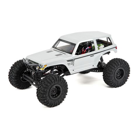
Axial RR10 Bomber User manual

COVER
INSTRUCTION MANUAL
AX90048-I001
AX90048-I001
BFGoodrich® Tires and Baja T/A® KR2 Trademarks are used under License from Michelin
Odyssey Battery trademark(s) is/are the property of EnerSys and affiliates

4
4
4
4
2

4
4
4
4
3

4 Close the battery tray and hood.
1 Turn on the transmitter. 2 Connect the battery.
3 Install the battery
Note:
Power to the vehicle is controlled
by connecting / disconnecting the
battery.
4
Make sure charger is correct for battery type selected for use.
Examples: Do NOT charge Lipo batteries with Nickel Metal Hydride
charger. Do NOT charge Nickel Cadmium batteries Lipo charger.
Stellen Sie sicher, Ladegerät ist korrekt für Batterietyp zur Verwendung ausgewählt.
Beispiele: Laden Sie keine Lipo-Akkus mit Nickel-Metall-Hydrid-Ladegerät. Laden Sie
keine Nickel-Cadmium-Akkus Lipo Ladegerät.
Assurez-vous que le chargeur est correcte pour le type de batterie sélectionné
à l'emploi. Exemples: Ne pas charger les batteries Lipo avec chargeur hydrure
métallique de nickel. Ne chargez pas les batteries au nickel-cadmium Lipo chargeur.

Steering Servo
C-Hub
Receiver Box
Steering
Transmission
Upper 4-link Bar
Shock Absorber
Spur/Pinion/Slipper
(Under Cover)
Motor 35T
Steering Knuckle
Driveshaft
Lower 4-link Bar
Battery Tray
Spare Tire Carrier
Differential
(inside axle housing)
Top View Parts
5

Getting-Started Checklist
The following checklist is a guide for getting you vehicle running for the first time.
Read ‘Cautions’ in Manual. (Page 2) Familiarize yourself with vehicle and
its components.
Even though the vehicle is new check
driveshaft setscrews and other screws to
make sure they are tight from the factory.
Charge battery pack. (Page 4) Install 4X AA batteries into Transmitter.
(Page 7)
Install battery pack in vehicle. (Page 4)
Check to make sure steering and throttle
operation work correctly. (Page 7)
Range check radio system. (Next Page)
Drive vehicle, challenge yourself and
have fun!
Maintain vehicle. (Next Page)
Turn on transmitter first,
then plug in battery
(power ESC) (Page 4)
6

6
KEEP CHASSIS FREE OF DIRT
OR DEBRIS
CHECK FOR LOOSE SCREWS
ON CHASSIS ESPECIALLY
THE KNUCKLE, C-HUB AND
AXLE LOCKOUT SCREWS
CHECK FOR WEAR ON
THE BALL JOINTS IN THE
STEERING AND SUSPENSION
LINKS
(REPLACE IF NECESSARY)
CHECK DRIVESHAFT SET
SCREWS AND RE-THREAD
LOCK IF NECESSARY
CHECK WHEEL NUTS MAKING
SURE THEY’RE SNUG
CHECK TIRES MAKING SURE
THE BEADS ARE STILL FIRMLY
BONDED TO THE ENTIRE
CIRCUMFERENCE OF THE RIM
REPLACE TRANSMITTER
AA’S IF THE GREEN LIGHT IS
BLINKING
INSPECT THE SPUR AND
PINION GEARS FOR DAMAGE
CHECK SLIPPER CLUTCH IF
APPLICABLE, FOR PROPER
OPERATION
(SEE PAGE 25 STEP
23 FOR SETUP INSTRUCTIONS)
CHECK DRIVELINE FOR
SMOOTH BIND-FREE
OPERATION
CHECK FOR ANY LOOSE
CONNECTIONS OR FRAYED
WIRING
INSPECT SHOCK
ABSORBERS FOR SMOOTH
DAMPENED OPERATION
CHECK RECEIVER ANTENNA
TO CONFIRM IT’S NOT
DAMAGED
CHECK STEERING
OPERATION FOR ANY BINDS
REPLACE ANY NOTICEABLE
BENT OR BROKEN PARTS
Maintaining Your Vehicle
Just like a full size car or truck your RC vehicle must undergo periodic maintenance in order to ensure peak running performance. Preventative
maintenance will also help avoid needless breakages which could result in costly repairs. Below are some suggestions to properly maintain
your vehicle.
Range-Checking Your Radio System
The radio system should be checked before operating the vehicle to ensure it’s operating properly and has adequate range.
1. Turn on the transmitter first and then the vehicle.
2. Have a friend hold the vehicle while keeping hands and loose clothing away from moving parts.
3. Walk away until you are at the farthest distance you plan to operate the vehicle.
4. Steer the vehicle back and forth and throttle both forward and reverse making sure there is no erratic behavior.
5. If any erratic behavior is exhibited do not operate the vehicle,call customer service for further assistance.
RANGE-CHECKING FOR DISTANCE
7

AE-5 Forward/Reverse ESC w/ Drag Brake
Roll Cage Removal
Mount the ESC in an area that is well ventilated and isolated from vibration and shock.
Connect the ESC motor wires to the motor red-red & black-black.
Plug the receiver with into the throttle channel on the receiver. The black negative wire should be
towards the outside of the receiver.
Before plugging the battery into the ESC, make sure your transmitter is on and the throttle trim is set at
zero.
Connect the battery to the ESC, this will turn on the ESC.
Test forward and reverse control using the transmitter.
To calibrate the ESC, make sure the transmitter is on and the throttle control is at neutral.
Connect the battery to the ESC and wait 3 seconds to let the ESC initiate a self-test and automatic
throttle calibration.
When the ESC is ready to run a long beep sound will be emitted from the motor.
Always disconnect the battery when the vehicle is not in use.
8

Pinion 56 60 64 68
11
28.85 30.91 32.97 35.03
12
26.44 28.33 30.22 32.11
13
24.41 26.15 27.90 29.64
14
22.67 24.88 25.90 27.52
21.15 22.67 24.18 25.69
19.83 21.25 22.67 24.08
18.67 20.00 21.33 22.67
15
16
17
Spur Gear
32 Pitch 38T/13T (Stock Gearing AX30392 or HD AX30395)
Pinion 56 60 64 68
11
32.64 34.97 37.31 39.64
12
29.92 32.06 34.20 36.33
13
27.62 29.59 31.57 33.54
14
25.65 27.48 29.31 31.14
23.94 25.65 27.36 29.07
22.44 24.04 25.65 27.25
21.12 22.63 24.14 25.65
15
16
17
Spur Gear
32 Pitch 43T/13T (Underdrive HD Gearing AX30402)
Pinion 56 60 64 68
11
25.38 27.19 29.00 30.81
12
23.26 24.92 26.58 28.25
13
21.47 23.01 24.54 26.07
14
19.94 21.36 21.94 22.60
19.61 19.94 21.27 22.60
17.45 18.69 19.94 21.18
16.42 17.59 18.77 19.94
15
16
17
Spur Gear
32 Pitch 36T/14T (Overdrive HD Gearing AX30401)
Final Drive Gear Ratio = (Spur/Pinion)x5.67
Gesamtubersetzung = (Spur/Pinion)x5.67
39.64:1
16.42:1
9
NOTES

Gear Mesh Adjustment
Suspension Tuning - Upper Link Adjustments
•Moving the upper links at the chassis
will change the anti-squat characteris-
tics of the vehicle under power.
•RTR Stock: Front upper hole, rear
middle hole.
•Optional holes, will create more or less
Anti-Squat for the rear traction under
power.
•Remove X2 M2.6x8mm AXA0413
Flatheads from AX31107 Spur Cover to
gain access to spur and pinion
•Loosen X2 M4x12mm AX31121
Capheads from AX31106 Motor Mount
Clamp
•Rotate the motor and motor mount
assembly to fine tune gear mesh
AXA0413
AXA0413
AX31121
AX31121
Rotate to adjust mesh
RTR
Option
Option
RTR
Option
Front
Rear
10
Other manuals for RR10 Bomber
2
Table of contents
Other Axial Toy manuals