AFA STAINLESS AFLZ01 User manual

MULTI-FUNCTION HAND HELD & RAIN HEAD SHOWER SYSTEM
AFA USA LLC
2450 Alton Parkway Irvine, CA 92606
Toll Free: (877) 778-6888
Monday-Saturday 8 a.m-6 p.m Pacic Time Zone
Email: customer.service@afastainless.com
Owners Manual
AFLZ01
Français P.23
Español P.45

AFA STAINLESS PRODUCT SUPPORT TEAM
Customer service hotline
Toll Free: (877) 778-6888
Monday-Saturday 8 a.m-6 p.m Pacic Time Zone
Email: customer.service@afastainless.com
AFA USA LLC
2450 Alton Parkway
Irvine, CA 92606
SAFETY INFORMATION
Please read and understand this entire manual before attempting to
assemble, operate or install the product. Before beginning the assembly of
this product, compare the parts with the package contents and list. If any
part is missing or damaged do not attempt to assemble the product and
contact AFA Stainless customer service for assistance.
WARNING
• Follow the installation instructions carefully. Proper installation is the
installer’s responsibility.
CAUTION
• Check local building codes before beginning installation to ensure
compliance.
This unit meets or exceeds the following:
• ASME A112.18.1
• CSA B125.1
• Listed by CUPC for use in the US and Canada
• Listed by California Energy Commission
California Title 20 Water-Efficiency Standards
2
Flow rate Showerhead max. 2.0 GPM
Flow rate Handshower max. 2.0 GPM
MULTI-FUNCTION HAND HELD & RAIN HEAD SHOWER SYSTEM
Owners Manual
AFLZ01

3
AFLZ01

4
DIMENSIONS:
(H)30.5" ×(W)13.75"
Hand shower hose: 59.05"
DRAWING
4"
8"
8"
23-5/8"
8-7/8"
30-1/2"
13-3/4"
6-1/3"
6-1/4"
25-1/5"
2-3/4"
2"

5
3
11
10
4
678910
1
2
1. 3-1/8" Supply Adapter
2. 4" Supply Adapter
3. Shower Arm
4. Shower Pipe
5. Adjustable Hand Shower Holder
6. Mounting Face Plate
7. Anchors
8. Screws
9. Bottom Mounting Bracket
10. Filter Gasket (Pre-installed)
11. Rain Shower Head
12. Hand Shower
13. Diverter Valve
SUPPLIES INCLUDED
T-1 Plumber’s Tape
T-2 1/2" Allen Wrench
T-3 3/32" Allen Wrench
T-4 Double Sided Tape ×2
PARTSLIST
5
13
12

6
BEFORE AFTER
min. 26"
Installation of this product requires the following:
1. Minimum distance of 6" between the middle of the supply adapter and the ceiling.
2. Minimum distance of 26" between the supply adapter and the top of the mixing valve trim.
Ceiling Ceiling
min.6"
BEFORE YOU BEGIN
IMPORTANT: please review before installation
Supply Adapter
Mixing Valve Trim
7
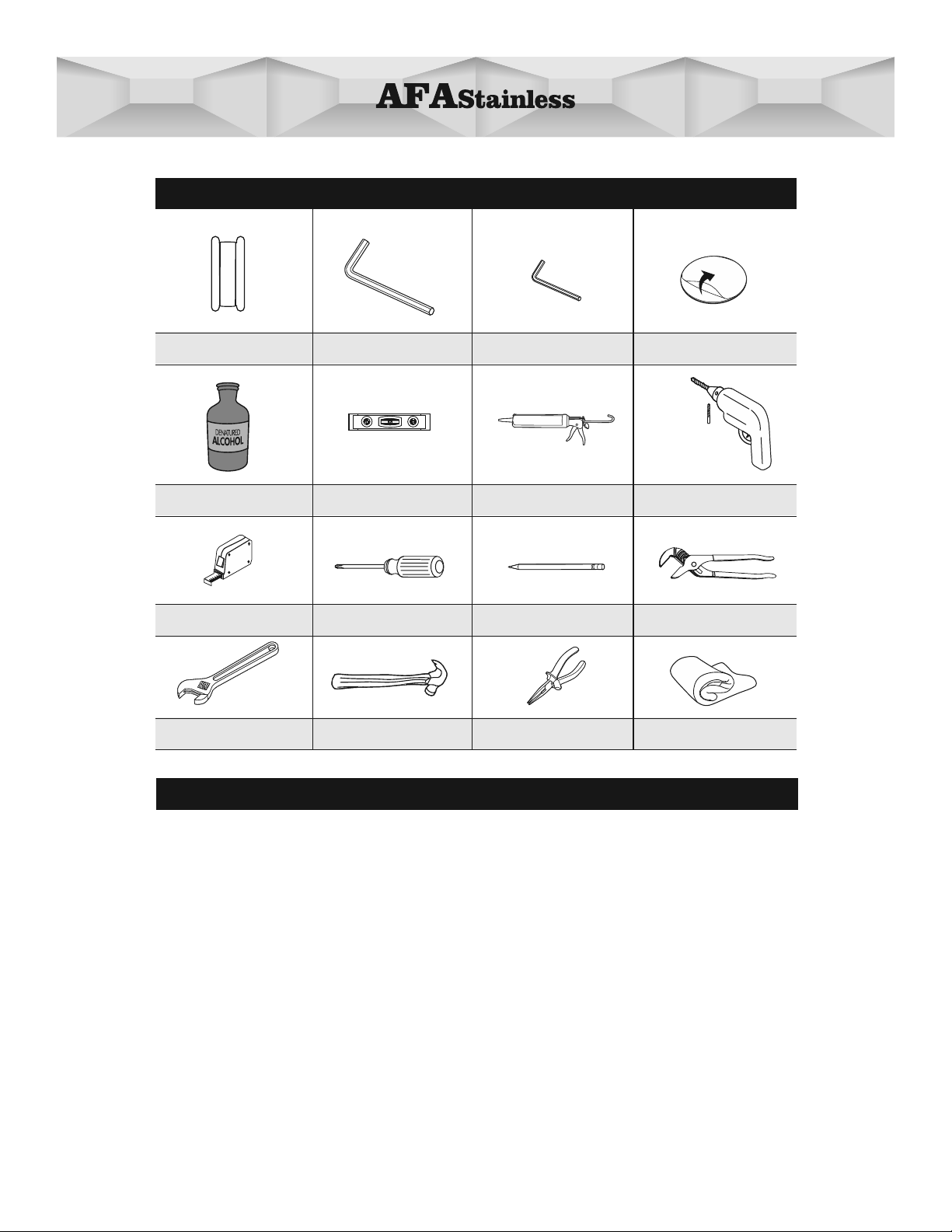
Recommended Tools for Installation:
Silicone SealantLevel
1/4 Inch Bit
Drill Bit
Electric Drill
T-5 T-6 T-7 T-8
Plumber’s Tape
Double Sided Tape ×2
T-1 (Included) T-2(Included) T-3(Included) T-4(Included)
Important Note for Installation
·Before and during installation, please read and familiarize yourself with all installation
instructions for this product.
·Please keep all components, parts and accessories of this product away from small
children and minors. During installation, all screws, tools and small parts should be
supervised so that they do not fall into the hands of children.
·Use caution at all times when installing this product. Please ensure that you are physically
able to perform all parts of the installation and that you have the correct tools and
equipment needed. Before beginning, remove all wrappers and packing materials
including staples and packing straps.
·Please check to ensure that all components and parts are complete.
·NOTE: The Filter Gasket parts #10 must be installed to protect against incoming
sediment as well as water leakage. It is recommended these gaskets be cleaned from
time to time. Please refer to page 19 & 20 “CLEANING AND CARE OF FILTER GASKET”.
Pencil Channel Lock Wrench
T-9 T-10 T-11 T-12
T-13 T-14
Adjustable Wrench
Tape Measure Phillips Screwdriver
1/2" Allen Wrench 3/32" Allen Wrench
Needle-nose Pliers
T-15
Denatured Alcohol
Cloth
T-16
Hammer

min 1-3/8"
Shower wall surface
3
21
21
T-7
INSTALLATION
CAUTION — TIPS FOR REMOVAL OF OLD SHOWER:
Always turn off water supply before removing existing diverter or disassembling the valve.
Open shower handle to relieve water pressure and ensure all water has been drained.
Option 1: Easy Install(No drilling required)
Measurethedistancebetweenthe
1/2”-14 NPT (National Pipe Thread)
in wall water supply elbow (not included)
and the nished wall surface.
If measurement is between 1-7/8”- 4”
then use supply adapter #2. If distance
is less than 1-3/8” choose 3-1/8”
supply adapter #1.
21
T-1
23
Wrap 1 (one) layer of Plumber’s Tape
T-1(Included) on the threaded side of
the Supply Adapter (1) or (2).
Insert one end of Shower Arm (3) into
Supply Adaptor (1) or (2).
Seal the wall around the elbow using
Silicon Sealant T-7 (Not included).
CAUTION: Failure to seal the wall
may result in water damage.
Connect the Supply Adapter (1) or (2)
and turn clockwise with 1/2" Allen
Wrench T-2 (Included).
56
4
8
1/2"
T-2
T-12
1
Remove the existing showerhead arm
by turning it in a counter clockwise
direction.
Note: A channel lock wrench T-12
(Not included) may be required.

Attach Bottom Mounting Bracket (9)
to the back of Diverter Valve (13).
Insert the Mounting Face Plate (6) into
the Bottom Mounting Bracket (9) and
tighten set screw using the 3/32” Allen
Wrench T-3 (Included).
Remove backing from Double Sided
Tape T-4 (Included) and attach to the
at side of Mounting Face Plate (6).
CAUTION: Do not touch the
adhesive side of tape.
3/32"
9
6
T-3
double sided tape
6
T-4
double sided tape
9
4
13
10 11 12
Slide shower arm ange so its ush
to wall.
Tighten Supply Adapter (1) or (2)with
set screw using 3/32" Allen Wrench
T-3 (Included).
3
T-6
7
3/32"
T-3
89
Use Level T-6 (Not included) to adjust
Shower Arm (3) to 90 degree.
9

13
4
9
3
4
14
4
3
15
Clean wall with Denatured Alcohol T-5
(Not included) and allow to fully dry. Insert Shower Pipe (4) into bottom of
Shower Arm (3).
Remove backing from Double Sided
Tape T-4 (Included).
CAUTION: Do not touch the adhesive
side.
3/32"
T-3
16 17
Use Level T-6 (Not included) to adjust
the bottom of diverter in a 90 degree
vertical position and press rmly to the
wall. Allow minimum of 4 hours for
proper adhesion.
Tighten set screw on the side of
Diverter Valve with 3/32" Allen Wrench
T-3 (Included).
Tighten set screw on the Shower
Arm (3) using the 3/32" Allen Wrench
T-3 (Included).
3/32"
9
13
T-3
18
10
Table of contents
Languages:
Other AFA Bathroom Fixture manuals