AeroFoam T-45 User manual
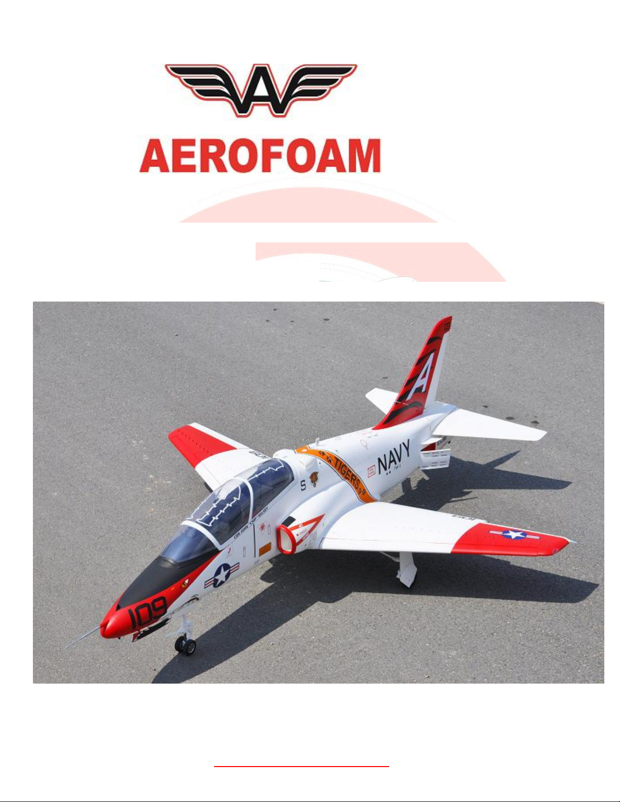
T-45
1/6.26th Scale
Length 69 inches Fuselage only (1753mm) (74.99 inches 1904mm with Pitot tube)
Wing Span 59.1 inches (1501 mm)
Weight RTF minus Fuel 16lbs (with AUT full)
Suggested Engine Size: 60n ~ 80n (8kg ~10kg) Perfect for our ACEx60 to ACEx80
CG 178mm (7 inches) from leading edge at root of wing to fuselage.
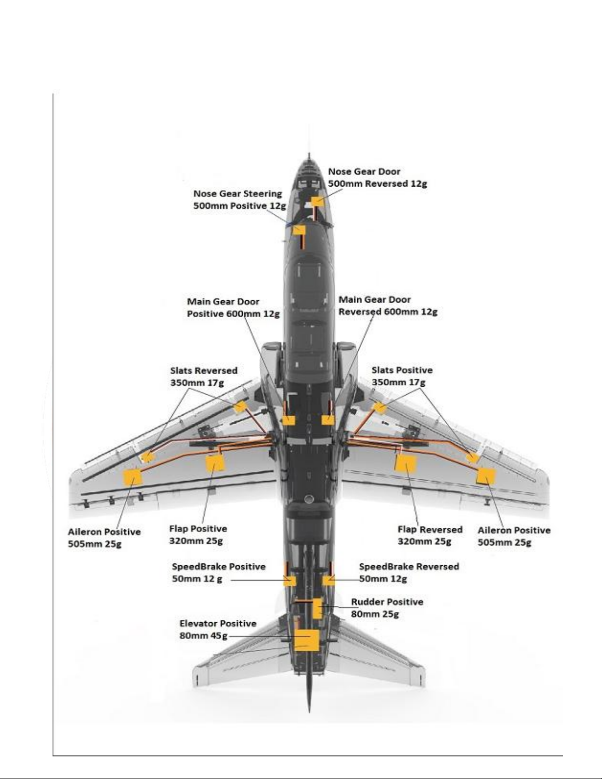
Ailerons Low 10mm / .40 inch Mid 12 / .47 inch High 14mm /.55 inch.
Flaps TakeOff 24mm Landing 40mm
Elevator low rate 19mm / .75 inch Mid 23mm / .90 inch High 26mm / 1.02inch.
Rudder Low 26mm / 1 inch High 38mm / 1.5 inch
Airbrake low 50mm high 85mm (do not operate at high Speed)
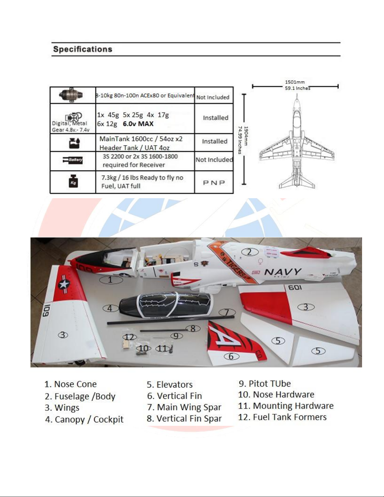
Kit Contents: Below is a basic rendition of the contents of the kit, your will have more hardware as
the pushrods would Not be installed at the factory and would be installed by the customer
The T-45 comes with the following servos:
1x 45g servo for Elevator
5x 25g servos for Aileron, Flaps and Rudder
4x 17g servos for Slats
6x 12g servos for Landing Gear doors, speed brakes and Steering
Use 6.0v MAX
CAUTION: When setting up and connecting the servos on your T-45 for the first time, be
careful not to have the Speed Brakes and the Flaps Binding or Reversed one example is to have
the model resting on a table and connecting power to the servos and have the Flap or Speed
Brakes in the Open position. You will burn out the servos. Be sure to check the FLAP,
Leading Edge Flaps / Slats and Speed Brake servos as soon as you
connect the Receiver power for the first time. AGAIN, You will
BURN OUT THE FLAP, LEADING EDGE FLAP / SLAT servos if your
transmitter is sending the servos in reverse direction. It is always
best to have those flying surfaces HALF DEPLOYED when you apply
power until you program those channels properly.
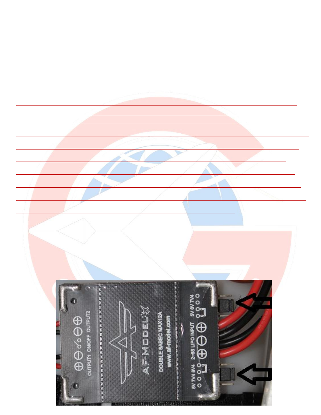
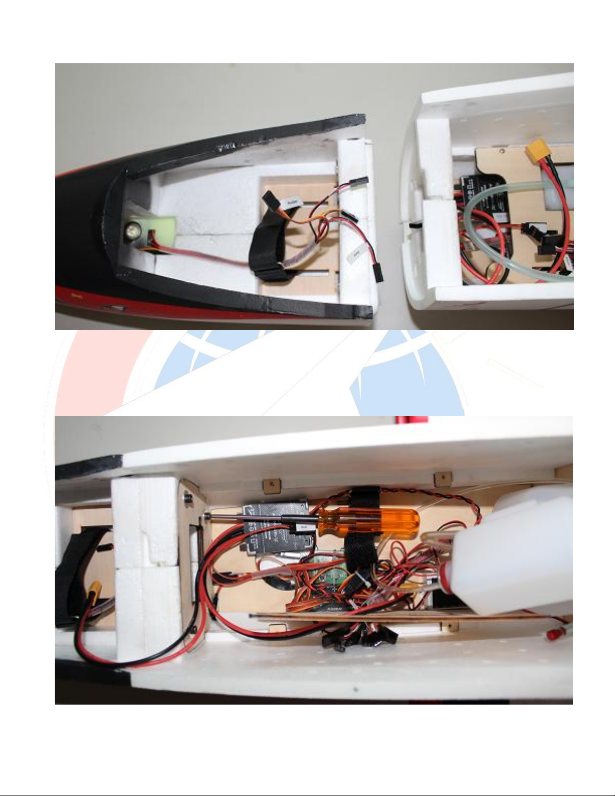
There is a EBEC already installed with two battery inputs, for 2x 3S batteries and also
two outputs, one is already connected to your Brakes and provides power for them at
7.4v the other lead is for your receiver and provides 6V please see the two black
selectors with the black arrows below and make sure they are as shown.
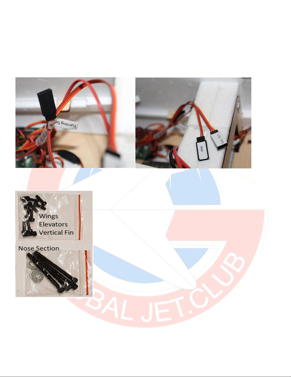
Nose section: There are four servo leads coming out of the nose section, make sure you pass them
through to the fuselage. Please note that some of the cables come with two wires and some with
three wires and you will have to match up the power wires when connecting them together.
There is a matching set of four servo cables under the canopy in their own wire bundle, find those
to connect with the cables in the nose section The four servo leads:
1. Gear for the nose retract 2. LED for the nose landing gear light.
3. Rudder (Nose Gear Steering servo) 4. Gear Door
Find the 4 Metric 4x50 (two inches long) screws and washers. You will need to insert those
through the main fuselage into the nose section. You only need to make sure the bolts are snug
enough until all the gap on the side of the fuselage is gone. Do not over tighten and crush the
foam.
Bring the nose section to the fuselage and Join the two using the 4x50 bolts. Insert
them from the fuselage into the nose section. You might find it easier in you remove
the main receiver tray, in this example the tray is just unbolted it and turned vertical
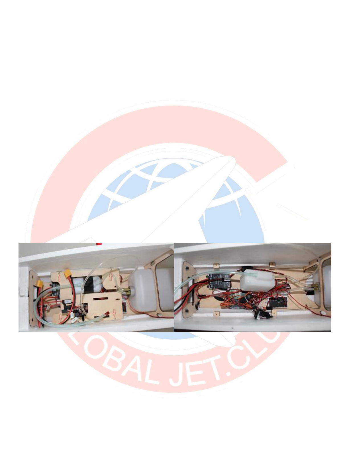
Fuel Tanks:
The Main Fuel tank is 1600cc / 54 Ounces; two of them are include. If you have
enough channels on your radio and you would also like to install a Smoke pump, the
top fuel tank position can be made to fit a 1600cc tank or a combination of Fuel and
Smoke as desired. On my prototype, I have a Dubro 20oz tank for fuel and a 10oz for
smoke, but bigger smoke tank can be installed.
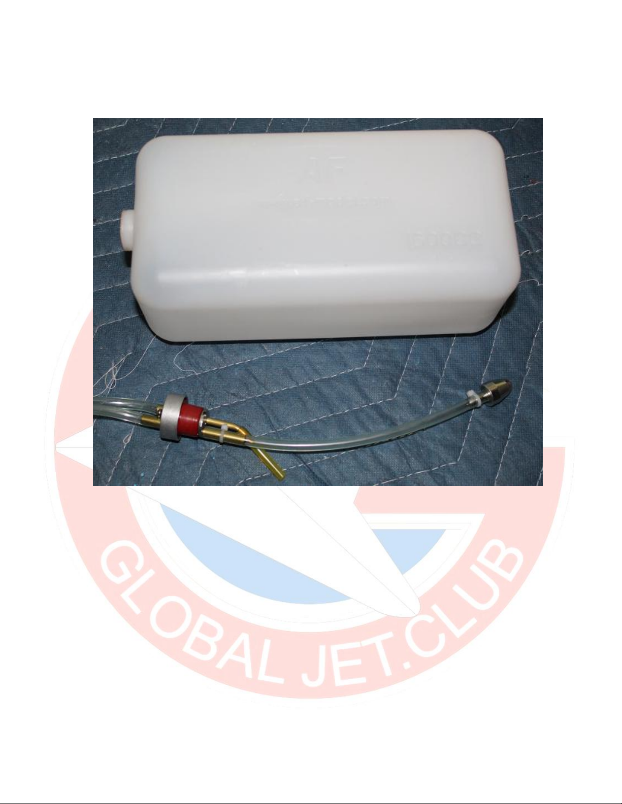
The fuel lines come installed on the tanks and for the most part, they are secured with
zip ties to tighten in place. This is OK, for beginners, but if you want to get into best
practices, you should install fuel barbs and safety wires all of your connections when
possible. While this is Not Required, it is a best practice to avoid spills or air bubbles
into your tanks. Below is how the standard tank arrives, two zip ties hold the fuel line
in place.
Begin by removing the Receiver tray in the nose, there are four small screws holding
the tray in, remove those to expose the UAT and all connections.
With the main tank and lines removed, it will look like the image below. This will work
properly, but as stated above, this it not the best practice for better reliability.
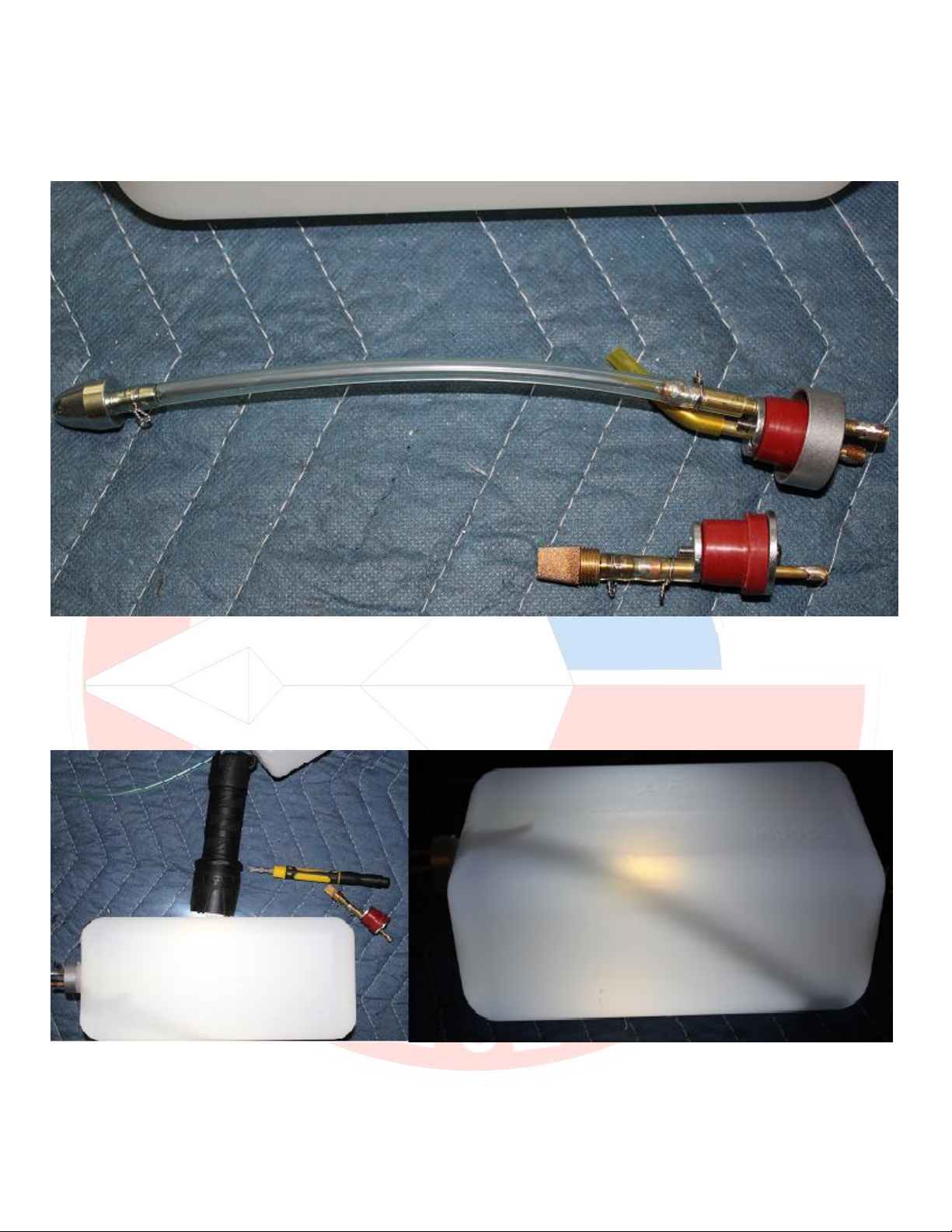
Now with best practices for Turbine operations, barbs installed on all the fuel lines
and then safety wire to hold the lines in place.
Fuel Tank Tip. If you can’t see the vent line and want to see how close it is to the top
of the tank, place a flashlight behind it and look though the opposite end. You can
accurately see how much wasted fuel space you will have before the fuel spills over.
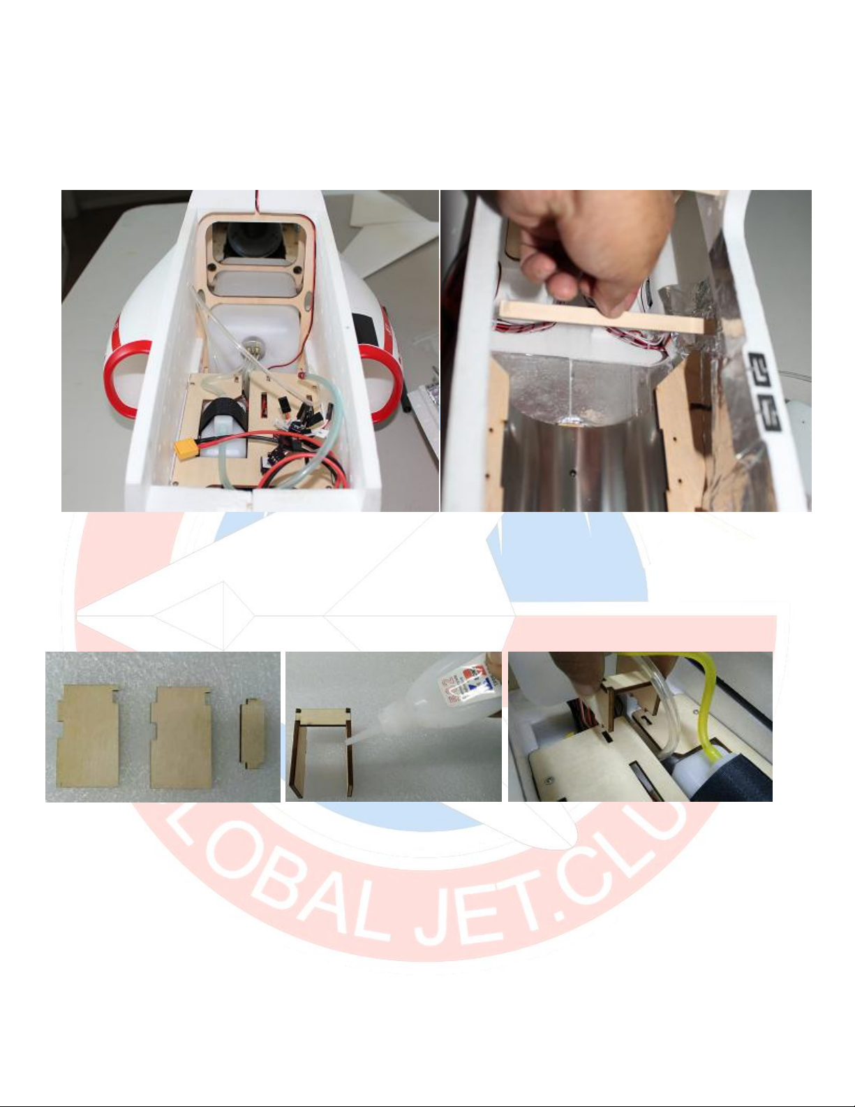
Below left is the picture of the stock bottom location. The picture on the right is how I
was able to remove the tank through the rear where the Turbine access hatch is
located, you will need to remove the mail fuel tank retainer / stopper brace.
The main tank is held in place with a wood stopper, assemble the three pieces of
wood and secure them with CyA to hold your main tank in place.
Other AeroFoam Toy manuals


