
ACT ACTpro 1520e User manual

ACTpro 1520e Single Door IP Controller
with 12 Volt DC 2A PSU
ACTpro 1500e Single Door IP Controller
Operating and Installation
Instructions
ACT Product Code: ACTpro 1520e & ACTpro 1500e
pro

1
The ACTpro 1520e and 1500e are compatible
with all ACTpro systems including:
4000 and 4200 controllers.

Copyright © 2016 Access Control Technology Ltd. Part No. 18-00099 Issue 1.0 2
ACTpro 1520e and ACTpro 1500e Operating & Installation Instructions
1.0 Typical wiring of ACTpro 1520e/1500e Controllers........................................... 4
2.0 Adding PIN and/or Proximity Readers ............................................................... 5
3.0 Connecting Controller to Ethernet. .................................................................... 6
4.0 Defaulting Controller and IP address Configuration......................................... 7
4.1 Factory Default ACTpro Controller (DIP Switch 2) ...................................... 7
4.2 DHCP/Static IP Addressing (DIP Switch 1) ................................................. 7
4.3 Defaulting the Static IP Address ................................................................. 8
4.4 Changing Static IP address on the ACTpro Controller................................ 8
5.0 Configuring the PC/Laptop for Static IP address ............................................. 9
6.0 ACTpro 1520e/1500e Controller status indicators ............................................ 10
7.0 Installing ACTenterprise ...................................................................................... 11
7.1 Download and extract the setup program .................................................. 11
7.2 Installing ACT Enterprise ............................................................................. 11
8.0 Add controllers to ACT Enterprise...................................................................... 12
9.0 Backup/Restore from ACT Enterprise ............................................................... 14
10.0 Troubleshooting.................................................................................................... 15
11.0 ACTpro 1520e Installation & Technical Specification ....................................... 16
12.0 Fire Override Configuration................................................................................. 19
13.0 Interlock/Airlock Configuration: ......................................................................... 19
14.0 Intruder Panel Wiring Diagram:........................................................................... 20
15.0 Product Specification .......................................................................................... 21
16.0 Ordering Information: .......................................................................................... 22

Copyright © 2016 Access Control Technology Ltd. Part No. 18-00099 Issue 1.0
3
ACTpro 1520e and ACTpro 1500e Operating & Installation Instructions
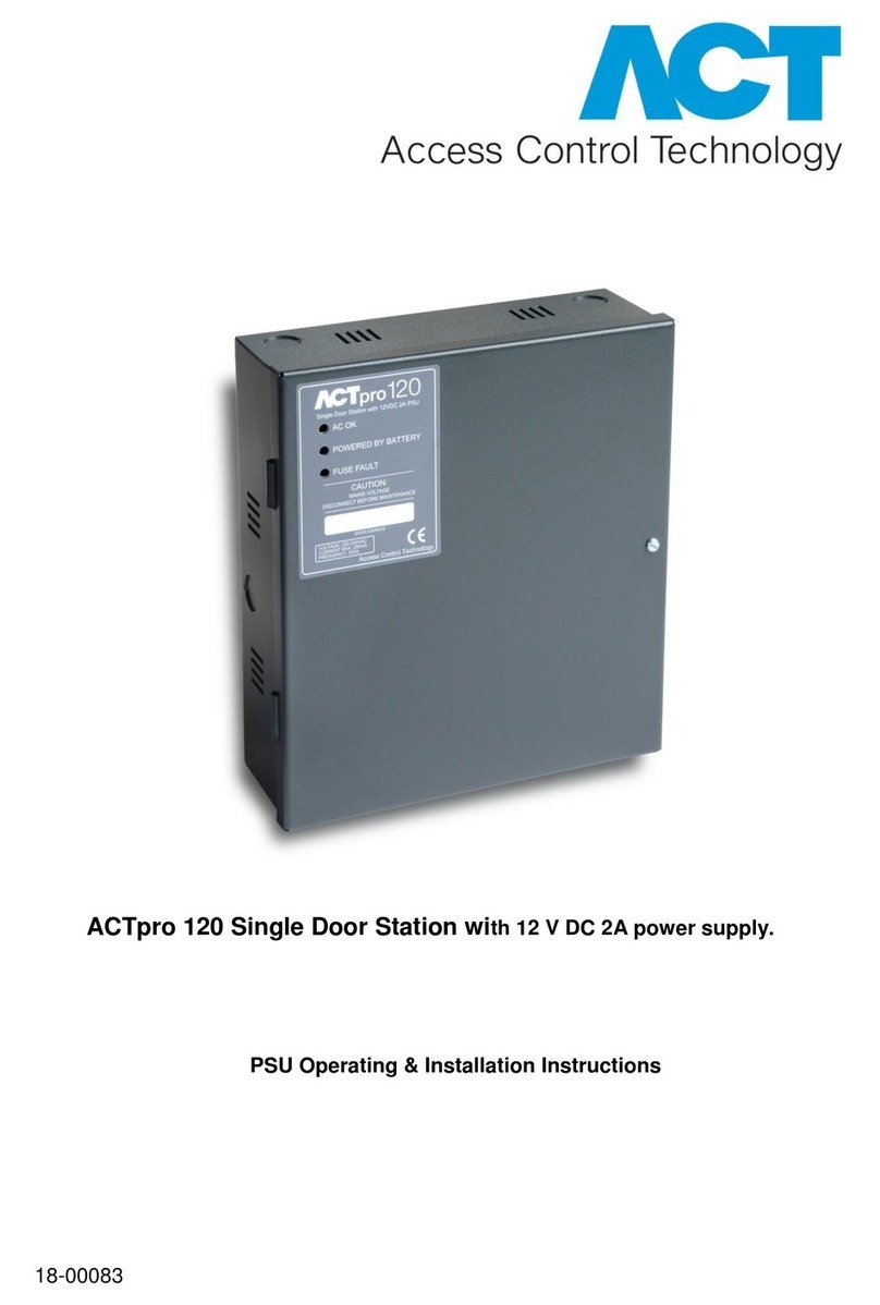
ACTpro 1520e PSU Installation guide
The ACTpro 1520e includes an ACT 12V DC 2A power supply unit.
The 2A output current is used to power the
controller and supply the battery recharge
current. 500mA is reserved for battery recharge
and to power the ACTpro Controller. Therefore
1.5A is available to power readers and the lock.
Example: Power budget of a typical single door
read in/out installation.
Note: See section 11 for ACTpro 1520e Installation & Technical Specification
Total Current Available 2000mA
ACTpro Controller and Battery Recharge 500mA
ACT Reader X 2 200mA
Typical Mag Lock 800mA
Total Consumption 1500mA
Spare Capacity 500mA

Copyright © 2016 Access Control Technology Ltd. Part No. 18-00099 Issue 1.0 4
ACTpro 1520e and ACTpro 1500e Operating & Installation Instructions
1.0 Typical wiring of ACTpro 1520e/1500e
RS485
BREAK GLASS UNIT
(Double Pole)
POLE A POLE B
DOOR
NETWORKS
DOOR
CONTACT
CONTROLLER
NETWORK
NC
C
NO
NC
C
NO
OP3
OP2
0V
AUX I
DC
PB
A
B
0V
A
B
0V
A
B
OV
0V
+12V
MAINS
PRESENT
B/GL
TAMP
IN OUT
2-16 DOORS 17-32 CTRL NW
1520e
WIRING DIAGRAM
W
G
B
R
BK
BN
Y
ACT READER WIRE
COLOUR CODING
NC
NO
C
NC
NO
C
12V 0V
0V PSU
IMPORTANT:
Place varistor across all lock terminals
AUX RELAY MAIN RELAY
AUX RELAY MAIN RELAY
AUX RELAY MAIN RELAY
AUX RELAY MAIN RELAY
AUX RELAY MAIN RELAY
AUX RELAY MAIN RELAY
AUX RELAY MAIN RELAY
AUX RELAY MAIN RELAY
AUX RELAY MAIN RELAY
AUX RELAY MAIN RELAY
Diagram shows normally energised Magnetic Lock
PUSH TO EXIT
RS485
Break Glass Monitoring
Normally Closed
OUT
IN
IN
OUT
IN
IN
ETHERNET: RJ45
To next IP controller or IP device.
Must be configured with correct
IP address.
RED
GREEN
DATA
+12V
OV
SENSE
CLOCK
Normally
Open
Normally
Closed
EXIT READERS
For Clock & Data readers, wire
exit readers in parallel but leave
the sense line unconnected.
For Wiegand readers, wire the
DATA 0 of the exit reader to SENSE
on the ACTpro 1520e.
Max length 100m with 12V DC
Cable: 8 Core Screened
Belden 9504 or equivalent
1 2
DHCP
DEFAULT
ON
OFF

Copyright © 2016 Access Control Technology Ltd. Part No. 18-00099 Issue 1.0
5
ACTpro 1520e and ACTpro 1500e Operating & Installation Instructions
2.0 Adding PIN and/or Proximity Readers
Wiring of entry & exit readers.
For Wiegand Entry Readers wire D0 to DATA Pin on ACTpro Controller and D1 to CLOCK
pin on ACTpro Controller.
For Wiegand Exit readers wire the D0 of the exit reader to SENSE pin on ACTpro controller
and D1 to CLOCK pin on ACTpro Controller.
SENSE
CLOCK
DATA
+12V
OV
RED
GREEN
Entry Reader
Exit Reader
(Do not connect to SENSE)
ACTpro 1050e
Pin & Proximity Reader
ACTpro 1030e
Proximity Reader
Reader Recommended Controller Signal information
Terminal wiring colour input Pin
Block
SENSE White SENSE For Entry readers connect the reader SENSE cable or
terminal to the SENSE input pin.
For Exit readers, do not use this input.
CLOCK Green CLOCK This is the clock or strobe signal input on the ACTpro
1520e/1500e. Connect the reader CLOCK cable or terminal
on the reader to CLOCK input pin.
DATA Blue DATA This is the Data input.
Connect the reader DATA cable or terminal on the reader
to DATA input pin.
+12V Red +12V Positive +12V DC Supply voltage for the reader.
0V Black 0V 0V Supply Voltage for the reader.
RED Brown RED Red LED control output from the ACTpro 1520e/1500e.
Connect the reader brown cable to the terminal marked
RED on the controller.
GREEN Yellow GREEN Green LED control output from the ACTpro 1520e/1500e.
Connect the reader green cable or terminal marked
GREEN on the ACTpro controller.

Copyright © 2016 Access Control Technology Ltd. Part No. 18-00099 Issue 1.0 6
ACTpro 1520e and ACTpro 1500e Operating & Installation Instructions
3.0 Connecting Controllers to customer LAN
Each ACTpro Controller can be connected directly to the customer network.
Max distance between devices 100m
Single doors connected over ethernet
LAN
Single doors connected over ethernet
LAN
Single doors connected over ethernet
Single doors connected over ethernet
Single doors connected over ethernet
Single doors connected over ethernet
From To Network
Type
Cable
Type
Comments
LAN ACTpro Controller TCP/IP Cat5/6 Max distance
between network
devices is 100m
ACTpro Controller ACTpro Readers ACT Protocol 8 core
Screen
Max distance 100m
ACTpro
1520e/1500e
ACTpro Controllers TCP/IP Cat5/6 Max distance
between network
devices is 100m
Cabling Chart
The ACTpro 1520e/1500e Controller has a dual Ethernet switch allowing for the
connection of IP devices. Ensure each controller has a unique IP address.

Copyright © 2016 Access Control Technology Ltd. Part No. 18-00099 Issue 1.0
7
ACTpro 1520e and ACTpro 1500e Operating & Installation Instructions
4.0 Defaulting Controller and IP Address Configuration
The ACTpro 1520e/1500e have two DIP switches.
• DIP switch 1: DHCP
Enables DHCP or Static IP address mode.
• DIP switch 2: DEFAULT
Defaults the controller or the Static IP address.
4.1 Factory Default controller (DIP Switch 2)
The ACTpro Controller may be defaulted to factory settings. This will completely erase the
controller memory. All information including card details will be erased and the static IP
address will be reset to 192.168.1.60.
To default the ACTpro Controller:
1. Power down the ACTpro Controller.
2. Set the DEFAULT DIP switch 2 to ON
3. Hold down the Tamper spring.
4. Apply power to the ACTpro 1520e/1500e controllers.
5. Wait approximately 5 seconds, until the controller conrms default completed
by sounding the buzzer.
6. Release the Tamper.
7. Power down the ACTpro controller.
8. Set the Default DIP switch to OFF
9. Re-apply power.
4.2 DHCP/Static IP Addressing (DIP Switch 1)
The ACTpro Controller is shipped with the DHCP enabled and can be congured to obtain
an IP address from a DHCP server or use a static IP address.
1. Power down the ACTpro Controller.
2. Set the DIP switch to its new position.
a. DHCP IP addressing: Move DIP switch 1 to ON
b. Static IP addressing: Move DIP switch 1 to OFF
Note: Default static IP address is 192.168.1.60
3. Re-apply power to the board.
1 2
DHCP
DEFAULT
ONOFF

Copyright © 2016 Access Control Technology Ltd. Part No. 18-00099 Issue 1.0 8
ACTpro 1520e and ACTpro 1500e Operating & Installation Instructions
4.3 Defaulting the Static IP address
The static IP address can be reset to the default value of 192.168.1.60.
1. Power down the ACTpro Controller.
2. Important: Ensure nothing is connected to the tamper input terminal and the tamper
spring is not pressed, otherwise the following steps will factory default the controller
losing all information.
3. Set the DHCP DIP switch 1 to OFF
4. Set the DEFAULT DIP switch 2 to ON.
5. Re-apply power - Wait approximately 5 seconds, until the controller conrms default
completed by sounding the buzzer.
6. Remove power.
7. Set the DEFAULT DIP switch 2 to OFF.
8. Re-apply power. Note: The static IP address can be changed via the web interface
or using ACT Software.
4.4 Changing Static IP address on the ACTpro Controller
1. Connect ACTpro Controller to the IP network.
2. Open Web browser on PC (use Microsoft Internet explorer, Chrome, etc.)
3. Enter http://ACT1520E-(NetBIOS address)
e.g. http://ACT1520E-07116
4. Logon details:
Username: installer
Password: 999999
5. Choose Communication menu and set the following:
• Static IP Address
• Network Mask
• Default Gateway
6. Press Save.
Note: use the new IP address
when connecting to the controller.

Copyright © 2016 Access Control Technology Ltd. Part No. 18-00099 Issue 1.0
9
ACTpro 1520e and ACTpro 1500e Operating & Installation Instructions
5.0 Configuring the PC/Laptop for Static IP address
For Microsoft Windows 7 users; go to Start and enter the “Network and Sharing” in the
search box.
For Microsoft Windows 8 or 10 users; start typing “Network and Sharing” from the main
screen.
1. Select “Network and
Sharing Centre”.
2. Select “Change adapter
setting” and Right click
on the “Local Area
Connection” and select
“Properties”.
3. Highlight “Internet Protocol
Version 4 (TCP/IPv4)” and press the
“Properties” button.
4. Select “Use the following IP address”
and enter the following:
Set IP address to “192.168.1.61”
Subnet mask to “255.255.255.0”
5. Press OK then Close.
This manual suits for next models
1
Table of contents
Other ACT Controllers manuals



Popular Controllers manuals by other brands

Digiplex
Digiplex DGP-848 Programming guide

YASKAWA
YASKAWA SGM series user manual

Sinope
Sinope Calypso RM3500ZB installation guide

Isimet
Isimet DLA Series Style 2 Installation, Operations, Start-up and Maintenance Instructions

LSIS
LSIS sv-ip5a user manual

Rockwell Automation
Rockwell Automation 1769-L31 installation instructions


