Wenger Signature Installation and operating instructions

Assembly/Owner’s Manual
Signature
®
Choral Riser
3-Step Model
ote: Please read and understand these Assembly and Owner’s Instructions before assembling
the parts.
ote: Remove all items from the shipping cartons and arrange them in a convenient location.
Refer to the illustrations on the following pages. If you need additional information,
contact the Wenger Corporation using the information below.
CONTENTS
©Wenger Corporation 2014 Printed in USA 05/14 Part #098E498-01
Wenger Corporation, 555 Park Drive, P.O. Box 448, Owatonna, Minnesota 55060-0448
Questions? Call.....USA: 800-4WENGER (493-6437) • Worldwide: 1-507-455-4100 • www.wengercorp.com
Safety Precautions . . . . . . . . . . . . . . . . . . . . . . . . . . . . . . . . .2
Warranty . . . . . . . . . . . . . . . . . . . . . . . . . . . . . . . . . . . . . . . . .2
Important User Information . . . . . . . . . . . . . . . . . . . . . . . . . . .3
General . . . . . . . . . . . . . . . . . . . . . . . . . . . . . . . . . . . . . .3
Manufacturer . . . . . . . . . . . . . . . . . . . . . . . . . . . . . . . . .3
Intended Use . . . . . . . . . . . . . . . . . . . . . . . . . . . . . . . . .3
Parts ist . . . . . . . . . . . . . . . . . . . . . . . . . . . . . . . . . . . . . . . . .4
Hardware Pack . . . . . . . . . . . . . . . . . . . . . . . . . . . . . . .4
Step Assembly . . . . . . . . . . . . . . . . . . . . . . . . . . . . . . . .5
Chassis Assembly . . . . . . . . . . . . . . . . . . . . . . . . . . . . .5
Stringer Assembly . . . . . . . . . . . . . . . . . . . . . . . . . . . . . .6
Back Rail Assembly . . . . . . . . . . . . . . . . . . . . . . . . . . . .6
Before Assembly . . . . . . . . . . . . . . . . . . . . . . . . . . . . . . . . . . .7
Assembly . . . . . . . . . . . . . . . . . . . . . . . . . . . . . . . . . . . . . . . .8
Chassis Assembly . . . . . . . . . . . . . . . . . . . . . . . . . . . . .8
Back Rail Assembly . . . . . . . . . . . . . . . . . . . . . . . . . . . .10
Step Assembly . . . . . . . . . . . . . . . . . . . . . . . . . . . . . . . .12
Final Assembly . . . . . . . . . . . . . . . . . . . . . . . . . . . . . . . .13
Safety Check . . . . . . . . . . . . . . . . . . . . . . . . . . . . . . . . .13
Moving and Storing Risers . . . . . . . . . . . . . . . . . . . . . . . . . . .14
Connecting Multiple Riser Units . . . . . . . . . . . . . . . . . . . . . . .15
Straight Configuration . . . . . . . . . . . . . . . . . . . . . . . . . . . . . . .16
Visit the Signature Choral Risers web page at www.wengercorp.com
for detailed instructions and videos.
2
SAFETY PRECAUTIONS
Make sure that anyone
workin on the Si nature
Choral Riser has read and
understands this manual.
!CAUTION
Failure to comply with
Warnin s and Cautions in
this document can result in
dama e to property or
serious injury.
!CAUTION
Throughout this manual you will find cautions and warnings which are defined as follows.
• WAR I G means that failure to follow the instruction may result in serious injury or death.
• CAUTIO means that failure to follow the instruction may result in serious injury or damage to
property.
Read all of the safety instructions before assembling or using the Signature Choral Riser.

3
IMPORTANT USER INFORMATION
GE ERAL
Copyright © 2014 by Wenger Corporation
All rights reserved. No part of the contents of this manual may be reproduced, copied, or transmitted in
any form or by any means including graphic, electronic, or mechanical methods or photocopying,
recording, or information storage and retrieval systems without the written permission of the publisher,
unless it is for the purchaser's personal use.
Printed and bound in the United States of America.
The information in this manual is subject to change without notice and does not represent a commitment
on the part of Wenger Corporation. Wenger Corporation does not assume any responsibility for any
errors that may appear in this manual.
In no event will Wenger Corporation be liable for technical or editorial omissions made herein, nor for
direct, indirect, special, incidental, or consequential damages resulting from the use or defect of this
manual.
The information in this document is not intended to cover all possible conditions and situations that might
occur. The end user must exercise caution and common sense when assembling or installing Wenger
Corporation products. If any questions or problems arise, call Wenger Corporation at 1-800-733-0393.
MA UFACTURER
The Signature®Choral Riser 3-Step Model is manufactured by:
Wenger Corporation
555 Park Drive
Owatonna, MN 55060
1-507-455-4100 • 1-800-733-0393
www.wengercorp.com
ITE DED USE
•This product is designed to be an elevation step for vocal groups.
•This product is intended for indoor use in normal ambient temperature and humidity conditions — it
must not be exposed to prolonged outside weather conditions.
•This product is intended to be assembled only as described in these instructions.
WARRA TY
This product is guaranteed free of defects in materials and workmanship for fifteen full years from
date of shipment. A full warranty statement is available upon request.
4
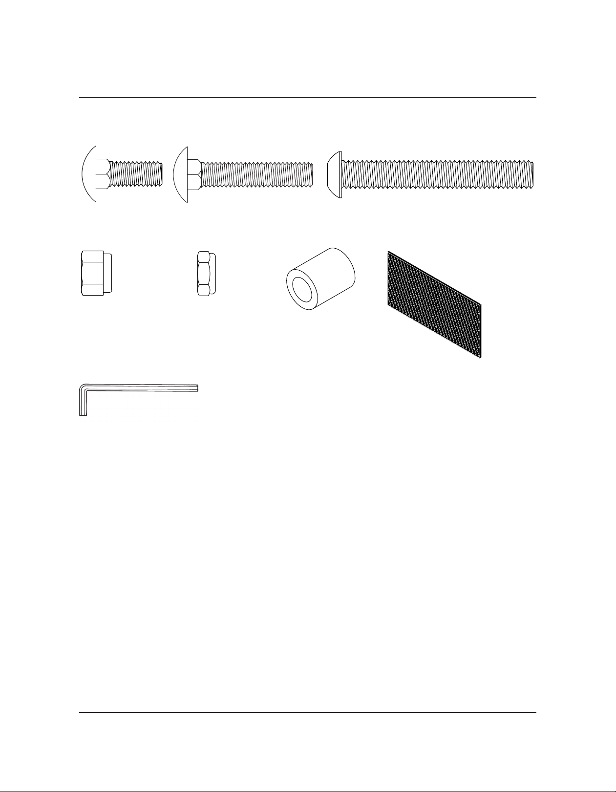
PARTS LIST
A 9/16” Socket or Combination Wrench is also required for assembly but is not supplied.
7/32" Hex Key Wrench
(supplied)
(2) Carriage Bolt,
3/8-16 x 1
HARDWARE PACK
(4) Socket Screw,
3/8-16 x 2-3/4
(2) Velcro Strip
Fasteners are shown actual size.
(8) ut, Lock,
3/8-16 (4) Carriage Sleeve
(6) ut, Jam Lock,
3/8-16
(For Use On Back Rail Only)
(2) Carriage Bolt,
3/8-16 x 1-3/4

7
5
Item Qty Description Item Qty Description
1 1 1st Step 5 2 Screw, SM, 1/4-20 x 1, Self Drill
2 1 2nd Step 6 2 Capscrew, GD2, ZP, 5/16-18 x 5/8
3 1 3rd Step 7 12 Wing Nut, 3/8-16
4 2 Unit Connector Bracket
1
2
3
4
6
5
PARTS LIST CONTINUED
STEP ASSEMBLY
CHASSIS ASSEMBLY
6
Item Qty Description Item Qty Description
1 1 3-Step Carriage 5 4 Carriage Bolt, 5/16-18 x 5/8
2 4 Caster 6 4 Carriage Bolt, 5/16-18 x 3/4
3 1 Back Rail Guide 7 10 Nut, ock, 5/16-18
4 8 Velcro oop, 1.75” 8 2 Truss Support
1
2
4
53
7
8

6
FASTENERS AND PARTS LIST CONTINUED
STRI GER ASSEMBLY
2
Item Qty Description Item Qty Description
1 2 Stringer Assembly 2 2 Plug, 1-1/4
1
BACK RAIL ASSEMBLY
2
1
Item Qty Description Item Qty Description
1 2 Back Rail Upright Tube 3 2 Back Rail End Cap
2 3 Back Rail Horizontal Tube 4 6 Plug, 1-1/4 OD
3
4
2
4
2
4

7
Each riser is shipped in two cartons, one shorter carton containing the chassis and the hardware pack
and one longer carton containing the Back Rail and Steps.
Assembling a riser will likely involve kneeling. Use carpeting, a rug, or the cardboard carton to soften a
hard floor and prevent scratching riser surfaces.
Risers should be assembled indoors, in a well-lighted space with a level floor. Choose an area close to
the performance space. Make sure risers will fit through doors between the assembly area and the
performance space.
One person can assemble a riser, but two people will make the job easier.
ATTENTION!!!
The following assembly instructions are intended for the risers to be used in an Arc Configuration.
For use in a Straight Configuration, alternating riser sets must be assembled with the Steps and Back
Rail reversed. See “Straight Configuration” on page 16.
BEFORE ASSEMBLY
Arc Configuration
Straight Configuration
Set up and use the riser only
on flat, solid surfaces.
!CAUTION

8
CHASSIS ASSEMBLY
1. Remove the Chassis Assembly, Stringer Assemblies, Truss Supports and Hardware Pack
from the carton. Place the Chassis Assembly (wheels down) on the floor.
2. Cut and remove the plastic shipping bands.
3. Position the Truss Support inside the Chassis Frame
with the square hole at the top and angled towards the outside.
4. Insert a 3/8-16 x 1” (short) Carriage Bolt
through both of the aligned holes from the
backside of the Chassis Assembly and the
Truss Support.
5. Secure both Carriage Bolts with a
3/8-16 ock Nut.
6. Rotate the Truss to align with the
square holes at the top of the Truss Supports.
7. Secure the Truss to the Truss Supports with
two 3/8-16 x 1-3/4” Carriage Bolts and
3/8-16 ock Nuts.
3/8-16
Lock ut
Chassis
Assembly
Truss Support
(square hole at the top)
3/8-16 x 1-3/4”
Carriage Bolt
3/8-16 x 1”
Carriage Bolt
Truss
3/8-16
Lock ut
ASSEMBLY

CHASSIS ASSEMBLY CO TI UED
8. Place both Stringer Assemblies on the threaded studs of the Chassis Assembly.
9. Place a Carriage Sleeve over each of the four threaded studs.
10. Secure the Stringer Assemblies and Sleeves using
a 3/8-16 ock Nut on each of the four threaded studs.
Tighten the ocking Nuts securely.
9
Stringer
Assembly
Completed
Chassis Assembly
Carriage
Sleeve
3/8-16
Lock ut
Threaded
Stud
ASSEMBLY CONTINUED

10
BACK RAIL ASSEMBLY
1. Remove the Upright Tubes, Horizontal Tubes and Steps from the carton.
2. Remove the End Caps from the bottom end of both Upright Tubes and set them aside.
Note: Do not discard the End Caps, they will be re-attached later.
3. Cut and remove the plastic band securing the Bracket
at the rear of both Stringer Assemblies.
4. Insert the open bottom end of one Upright Tube
into the Guide Plate.
5. Attach the Upright Tube to the Bracket with
two 3/8-16 x 2-3/4” Socket Screws.
Note: It may be necessary to lift up
on the Chassis Assembly sli htly
to et the Screws started.
6. Repeat steps 4 and 5 for the other
Upright Tube.
7. Securely tighten all four Screws.
.
Upright
Tubes
End
Caps
Plastic Band &
Bracket Location
Guide
Plate
ASSEMBLY CONTINUED
3/8-16 x 2-3/4”
Socket Screws
Table of contents
Other Wenger Ladder manuals


