Velocitek SC-1 User manual

SC-1 Reference Manual
Firmware Version 2.4F (Full Functionality)

Contents
INTRODUCTION 1
SC-1 FEATURES 1
MANUAL ORGANIZATION 1
ON THE WATER 2
DEVICE OVERVIEW 2
DISPLAYS 2
BUTTONS 3
BATTERY LIFE INDICATOR 4
GETTING STARTED 5
INSERTING BATTERIES 5
LOCK FEATURE 6
UNLOCKING PROCEDURE 7
TURNING POWER ON8
TURNING POWER OFF 9
SIGNAL ACQUISITION 10
OPERATING MODES 11
LOWER DISPLAY MODE SELECTION 12
UPPER DISPLAY MODE SELECTION 13
SPEEDOMETER MODE 14
COMPASS MODE 16
TACTICAL COMPASS MODE 19
VMG MODE 23
TIMER MODE 26
START LINE PROXIMITY MODE 31
DATA LOGGER MODE 35
WHEN YOU GET HOME 36
SOFTWARE INSTALLATION REQUIRED TO DOWNLOAD GPS DATA FROM YOUR DEVICE 36
INSTALLING CONTROL CENTER 36
INSTALLING DRIVERS FOR YOUR VELOCITEK DEVICE 50
USING CONTROL CENTER 54
SC-1 GPS DATA STORAGE 54
DOWNLOADING GPS DATA 55

SAVING GPS DATA 59
CLEARING GPS DATA 67
UPDATING USER INFORMATION 68
UPDATING DEVICE SETTINGS 69
UPDATING FIRMWARE 72
LAUNCHING GPS ACTION REPLAY FROM CONTROL CENTER 74
MAINTENANCE 75
CONTACT 76
INDEX 77

SC-1 Features 1
Introduction
SC-1 Features
The SC-1 is a powerful sail training tool designed to provide you with the feedback you need to sail
faster. The SC-1 has the following features:
Speed, compass, tactical compass, VMG and start line proximity updated at 2 times a second
Start timer with user configurable timer rollover and start sequence
Ability to display any two measurements simultaneously
Maximum and best 10 second average speed recall
Adjustable damping
Up to 20 hours of battery life
User configurable device settings allow customization of select SC1 functionalities
Over 20 hours of GPS data storage at record rate of every 2 seconds
Data downloading through a USB link
Downloaded data is easily formatted for use with Kattack, Google Earth and GPS Action Replay
Internet updatable firmware allows you to benefit from ongoing product improvements and
feature additions
Manual Organization
This manual is divided into 2 main sections. The first section, On The Water describes how to use the
SC-1 to obtain real-time feedback while you are sailing. The second section, When You Get Home
describes how to download and view GPS data from your SC-1 using a PC.

Device Overview 2
On the Water
Device Overview
Displays
The following diagram shows the SC-1's two main display areas:
The upper and lower displays can both be used to display speed, heading, tactical heading, VMG, start
line proximity or timer information. The information shown on each display is made clear by a mode
indicator immediately to the left of the numerical display area. There is no “TIMER” indicator on the
upper display. Timer mode on the upper display is indicated simply by the presence of a colon between
the minutes and seconds. Additionally there is no start line proximity mode indicator in both upper and
lower display. No mode indicators will be displayed in either screen when the device is in start line
mode. Tactical compass mode is indicated by presence of both "COMPASS" and "VMG" indicators.
The first decimal point on the upper display is used as an unlock indicator if any of the lock features are
enabled. The indicator is not displayed if all lock features are disabled.

Device Overview 3
Buttons
The SC-1 is controlled by four different capacitive touch sensors. These touch sensors detect the
presence of your thumbs when they are placed on top of the regions shown in the following diagram:
The captions on the above diagram indicate how the different touch sensors will be referred to in the
rest of this manual.

Device Overview 4
Battery Life Indicator
The battery life indicator is located in the top left corner of the SC-1. As the energy in the device's
batteries is consumed, the battery life indicator will undergo the following progression to show you how
much run time you have left:
1 When the indicator is fully illuminated you have approximately 20 hours of battery life remaining.
2 When the indicator is two thirds illuminated you have less than 15 hours of battery life remaining.
3 When the indicator is one third illuminated you have less than 10 hours of battery life remaining.
4 When the indicator is not illuminated you have less than 5 hours of battery life remaining.
When the batteries are too low to properly power the GPS chipset the whole display will go blank and
flash "LO" in the lower display.
Note: The above applies for rechargeable nickel metal hydride (NiMH) batteries. Disposable alkaline
batteries will provide approximately half the life of NiMH batteries. Also with disposable batteries,
there will be a tendency for the life indicator to remain fully illuminated for most of the battery life and
only drop down to the lower levels when the batteries are nearly exhausted.
The SC-1 will slowly deplete batteries even when it is turned off. Fully charged batteries will be
exhausted in about 100 days when the device is left turned off. For long term storage, remove any one
of the three batteries from the device to prevent this slow drain.

Getting Started 5
Getting Started
Inserting Batteries
Open the waterproof case and insert three AA batteries into the metal clips on the circuit board. Be
careful to orient the batteries according to the polarity markings on the circuit board. These markings are
circled in red on the following photograph:
The SC-1 will work with rechargeable nickel metal hydride (NiMH) batteries or standard disposable AA
batteries. Disposable batteries will provide approximately 10 hours of life while rechargeable NiMH
batteries will last for 20 hours or longer. The remaining battery life indicator on the SC-1 is calibrated
to work with rechargeable NiMH batteries.

Getting Started 6
Lock Feature
The Velocitek SC-1 uses touch sensors to accept user input. Splashing water can trigger the touch
sensors. To prevent the device from being inadvertently controlled by splashing water the user can
enable lock features. When the device is locked, buttons are non-functional. There are two lock
features:
Speed Lock: The unit locks when the device speed exceeds the speed lock value (knots).
During speed lock, the unit will not allow the user to unlock the buttons.
Timeout Lock: The unit locks when the buttons have been inactive for a time period over the
timeout lock value (seconds). During a timeout lock, the unit allows the user to unlock the
buttons.
Speed lock enable, speed lock value, timeout lock enable and timeout lock value are all configurable in
device settings. The speed lock and timeout lock can be enabled independently.
The device will lock in response to the following events if timeout lock is enabled:
The timer is started
The timer is synchronized
When both lock features are disabled, the unlock indicator is never shown.

Getting Started 7
Unlocking Procedure
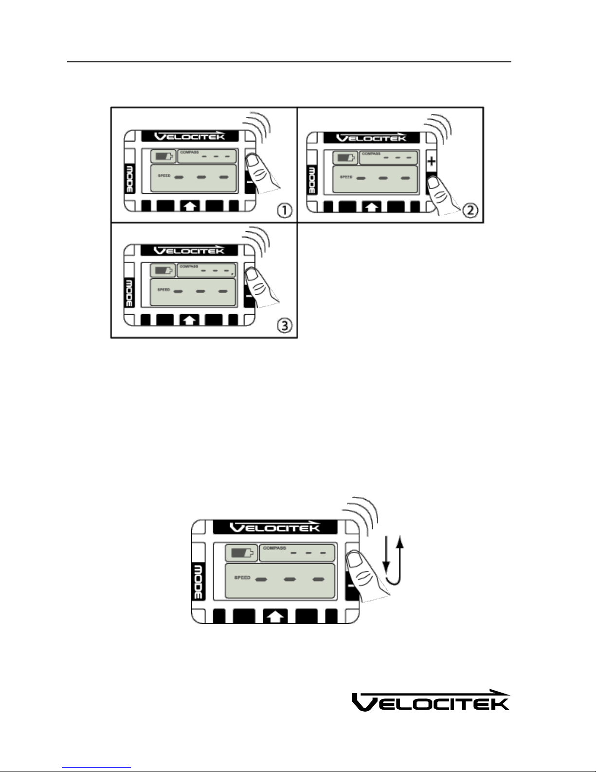
1 Cover the plus button with your thumb.
2 When you hear a beep, move your thumb to the minus button.
3 When you hear another beep, move your thumb back to the plus button. A long beep indicates
that you have successfully unlocked the device. The unlock indicator will be displayed if the lock
feature is enabled. All buttons will now respond to your input.
The unlocking procedure can be executed very quickly by sliding your thumb back and forth over the plus
and minus buttons as shown below:
Other manuals for SC-1
2
Table of contents
Other Velocitek Boating Equipment manuals
Popular Boating Equipment manuals by other brands

Dowco
Dowco V322 CC - 2019 installation instructions

Humphree
Humphree HCS-5 installation manual

Vetus
Vetus BOW4512D Operation manual and installation instructions

Dock Doctors
Dock Doctors SLIDING BOARDING STEP Assembly instructions

Mastervolt
Mastervolt Mass Combi 12/2000-100 Quick installation

Zattini Group
Zattini Group bamar BOXTRON E14S Use and maintenance instruction manual