
Vega VEGAPULS 61 User manual

Quick setup guide
Radar sensor for continuous level
measurement of liquids
VEGAPULS 61
Probus PA
Approval according to LPR radio standard
Document ID: 47106

2
Contents
VEGAPULS 61 • Probus PA
47106-EN-210621
Contents
1 For your safety ......................................................................................................................... 3
1.1 Authorised personnel ....................................................................................................... 3
1.2 Appropriate use................................................................................................................ 3
1.3 Warning about incorrect use............................................................................................. 3
1.4 General safety instructions............................................................................................... 3
1.5 EU conformity................................................................................................................... 4
1.6 NAMUR recommendations .............................................................................................. 4
1.7 Radio license for Europe .................................................................................................. 4
1.8 Environmental instructions ............................................................................................... 5
2 Product description ................................................................................................................. 6
2.1 Conguration.................................................................................................................... 6
3 Mounting................................................................................................................................... 7
3.1 Collar or adapter ange.................................................................................................... 7
3.2 Mounting preparations, mounting strap............................................................................ 7
3.3 Mounting instructions ....................................................................................................... 8
4 Connecting to the bus system.............................................................................................. 10
4.1 Connecting..................................................................................................................... 10
4.2 Wiring plan, single chamber housing.............................................................................. 11
4.3 Wiring plan, double chamber housing ............................................................................ 11
5 Set up with the display and adjustment module ................................................................ 13
5.1 Insert display and adjustment module............................................................................ 13
5.2 Parameter adjustment .................................................................................................... 14
5.3 Menu overview ............................................................................................................... 17
6 Set up with smartphone/tablet, PC/notebook via Bluetooth ............................................. 19
6.1 Preparations................................................................................................................... 19
6.2 Connecting..................................................................................................................... 20
6.3 Sensor parameter adjustment........................................................................................ 20
7 Supplement ............................................................................................................................ 22
7.1 Technical data ................................................................................................................ 22
Information:
This quick setup guide enables quick setup and commissioning of
your instrument.
You can nd supplementary information in the corresponding, more
detailed Operating Instructions Manual as well as the Safety Manual
that comes with instruments with SIL qualication. These manuals are
available on our homepage.
Operating instructions VEGAPULS 61 - Probus PA - Approval
according to LPR radio standard; Document-ID 41715
Editing status of the quick setup guide: 2021-06-10

3
1 For your safety
VEGAPULS 61 • Probus PA
47106-EN-210621
1 For your safety
1.1 Authorised personnel
All operations described in this documentation must be carried out
only by trained, qualied personnel authorised by the plant operator.
During work on and with the device, the required personal protective
equipment must always be worn.
1.2 Appropriate use
VEGAPULS 61 is a sensor for continuous level measurement.
You can nd detailed information about the area of application in
chapter " Product description".
Operational reliability is ensured only if the instrument is properly
used according to the specications in the operating instructions
manual as well as possible supplementary instructions.
1.3 Warning about incorrect use
Inappropriate or incorrect use of this product can give rise to applica-
tion-specic hazards, e.g. vessel overll through incorrect mounting
or adjustment. Damage to property and persons or environmental
contamination can result. Also, the protective characteristics of the
instrument can be impaired.
1.4 General safety instructions
This is a state-of-the-art instrument complying with all prevailing
regulations and directives. The instrument must only be operated in a
technically awless and reliable condition. The operator is responsi-
ble for the trouble-free operation of the instrument. When measuring
aggressive or corrosive media that can cause a dangerous situation
if the instrument malfunctions, the operator has to implement suitable
measures to make sure the instrument is functioning properly.
The safety instructions in this operating instructions manual, the na-
tional installation standards as well as the valid safety regulations and
accident prevention rules must be observed by the user.
For safety and warranty reasons, any invasive work on the device
beyond that described in the operating instructions manual may be
carried out only by personnel authorised by the manufacturer. Arbi-
trary conversions or modications are explicitly forbidden. For safety
reasons, only the accessory specied by the manufacturer must be
used.
To avoid any danger, the safety approval markings and safety tips on
the device must also be observed.
The low transmitting power of the radar sensor is far below the inter-
nationally approved limits. No health impairments are to be expected
with intended use. The band range of the measuring frequency can
be found in chapter " Technical data".

4
1 For your safety
VEGAPULS 61 • Probus PA
47106-EN-210621
1.5 EU conformity
The device fulls the legal requirements of the applicable EU direc-
tives. By axing the CE marking, we conrm the conformity of the
instrument with these directives.
The EU conformity declaration can be found on our homepage.
Electromagnetic compatibility
Instruments in four-wire or Ex-d-ia version are designed for use in an
industrial environment. Nevertheless, electromagnetic interference
from electrical conductors and radiated emissions must be taken into
account, as is usual with class A instruments according to EN 61326-
1. If the instrument is used in a dierent environment, the electromag-
netic compatibility to other instruments must be ensured by suitable
measures.
1.6 NAMUR recommendations
NAMUR is the automation technology user association in the process
industry in Germany. The published NAMUR recommendations are
accepted as the standard in eld instrumentation.
The device fulls the requirements of the following NAMUR recom-
mendations:
• NE 21 – Electromagnetic compatibility of equipment
• NE 53 – Compatibility of eld devices and display/adjustment
components
• NE 107 – Self-monitoring and diagnosis of eld devices
For further information see www.namur.de.
1.7 Radio license for Europe
The instrument was tested according to the latest issue of the follow-
ing harmonized standards:
• EN 302372 - Tank Level Probing Radar
• EN 302729 - Level Probing Radar
It is hence approved for use inside and outside closed vessels in
countries of the EU.
Use is also approved in EFTA countries, provided the respective
standards have been implemented.
For operation inside of closed vessels, points a to f in annex E of
EN 302372 must be fullled.
For operation outside of closed vessels, the following conditions must
be fullled:
• The installation must be carried out by trained qualied personnel
• The instrument must be stationary mounted and the antenna
directed vertically downward
• The mounting location must be at least 4 km away from radio
astronomy stations, unless special permission was granted by the
responsible national approval authority

5
1 For your safety
VEGAPULS 61 • Probus PA
47106-EN-210621
• When installed within 4 to 40 km of a radio astronomy station,
the instrument must not be mounted higher than 15 m above the
ground.
You can nd a list of the respective radio astronomy stations in chap-
ter " Supplement".
1.8 Environmental instructions
Protection of the environment is one of our most important duties.
That is why we have introduced an environment management system
with the goal of continuously improving company environmental pro-
tection. The environment management system is certied according
to DIN EN ISO 14001.
Please help us full this obligation by observing the environmental
instructions in this manual:
• Chapter " Packaging, transport and storage"
• Chapter " Disposal"

6
2 Product description
VEGAPULS 61 • Probus PA
47106-EN-210621
2 Product description
2.1 Conguration
The type label contains the most important data for identication and
use of the instrument:
2
1
15
13
14
12
11
5
3
6
4
7
8
10
9
Fig. 1: Layout of the type label (example)
1 Instrument type
2 Product code
3 Approvals
4 Power supply and signal output, electronics
5 Protection rating
6 Measuring range
7 Process and ambient temperature, process pressure
8 Material wetted parts
9 Hardware and software version
10 Order number
11 Serial number of the instrument
12 Data matrix code for VEGA Tools app
13 Symbol of the device protection class
14 ID numbers, instrument documentation
15 Reminder to observe the instrument documentation
The type label contains the serial number of the instrument. With it
you can nd the following instrument data on our homepage:
• Product code (HTML)
• Delivery date (HTML)
• Order-specic instrument features (HTML)
• Operating instructions and quick setup guide at the time of ship-
ment (PDF)
• Order-specic sensor data for an electronics exchange (XML)
• Test certicate (PDF) - optional
Move to " www.vega.com" and enter in the search eld the serial
number of your instrument.
Alternatively, you can access the data via your smartphone:
• Download the VEGA Tools app from the " Apple App Store" or the
" Google Play Store"
• Scan the DataMatrix code on the type label of the instrument or
• Enter the serial number manually in the app
Type label
Serial number - Instru-
ment search

7
3 Mounting
VEGAPULS 61 • Probus PA
47106-EN-210621
3 Mounting
3.1 Collar or adapter ange
For mounting the instrument on a nozzle, a combi compression ange
for DN 80 (ASME 3" or JIS 80) is also available for retrotting. Option-
ally, the instrument can be also equipped with an adapter ange from
DN 100 (ASME 4" or JIS 100).
With the housing versions plastic, aluminium single chamber and
stainless steel, the collar ange can be placed directly over the hous-
ing. With the aluminium double chamber housing, retroactive mount-
ing in this way is not possible - the mounting type must be specied
with the order.
You can nd drawings of these mounting options in chapter " Dimen-
sions".
Fig. 2: Flange mounting of the radar sensor
3.2 Mounting preparations, mounting strap
The mounting strap enables simple mounting on the vessel wall or
silo top. It is suitable for wall, ceiling or boom mounting. Especially in
open vessels this is a very easy and eective way to align the sensor
to the bulk solid surface.
The strap is supplied unassembled and must be screwed to the
sensor before setup with three hexagon socket screws M5 x 10 and
spring washers. Max. torque, see chapter " Technical data". Required
tools: Allen wrench size 4.
There are two ways to screw the strap onto the sensor. Depending
on the selected version, the sensors can be swivelled in the strap as
follows:
• Single chamber housing

8
3 Mounting
VEGAPULS 61 • Probus PA
47106-EN-210621
– Angle of inclination 180°, innitely variable
– Angle of inclination in three steps 0°, 90° and 180°
• Double chamber housing
– Angle of inclination 90°, innitely variable
– Angle of inclination in two steps 0° and 90°
Fig. 3: Adjustment of the angle of inclination
Fig. 4: Turning by fastening in the centre
3.3 Mounting instructions
1. Distance from the vessel wall > 200 mm, the antenna should
protrude > 10 mm into the vessel
> 200 mm
(7.87
")
Fig. 5: Distance of the antenna to the vessel wall/vessel ceiling
2. Note min. socket diameter depending on the socket length
Mounting

9
3 Mounting
VEGAPULS 61 • Probus PA
47106-EN-210621
For further information see chapter " Mounting".
10
4 Connecting to the bus system
VEGAPULS 61 • Probus PA
47106-EN-210621
4 Connecting to the bus system
4.1 Connecting
The voltage supply and signal output are connected via the spring-
loaded terminals in the housing.
Connection to the display and adjustment module or to the interface
adapter is carried out via contact pins in the housing.
Information:
The terminal block is pluggable and can be removed from the
electronics. To do this, lift the terminal block with a small screwdriver
and pull it out. When reinserting the terminal block, you should hear it
snap in.
Proceed as follows:
1. Unscrew the housing lid
2. If a display and adjustment module is installed, remove it by turn-
ing it slightly to the left
3. Loosen compression nut of the cable gland and remove blind
plug
4. Remove approx. 10 cm (4 in) of the cable mantle, strip approx.
1 cm (0.4 in) of insulation from the ends of the individual wires
5. Insert the cable into the sensor through the cable entry
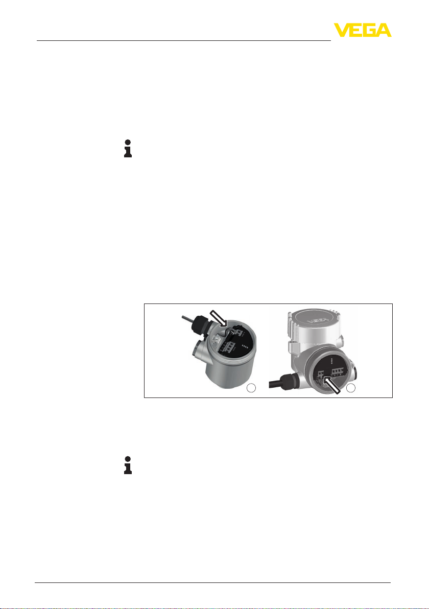
1 2
Fig. 6: Connection steps 5 and 6
1 Single chamber housing
2 Double chamber housing
6. Insert the wire ends into the terminals according to the wiring plan
Note:
Solid cores as well as exible cores with wire end sleeves are insert-
ed directly into the terminal openings. In case of exible cores without
end sleeves, press the terminal from above with a small screwdriver,
the terminal opening is then free.When the screwdriver is released,
the terminal closes again.
7. Check the hold of the wires in the terminals by lightly pulling on
them
8. Connect the shielding to the internal ground terminal, connect the
external ground terminal to potential equalisation
Connection technology
Connection procedure
Other manuals for VEGAPULS 61
16
Table of contents
Other Vega Accessories manuals

Vega
Vega VEGAPULS 69 User manual

Vega
Vega VEGAFLEX 81 User manual

Vega
Vega VEGAPULS 61 User manual

Vega
Vega VEGAFLEX 86 User manual

Vega
Vega VEGAPULS 21 User manual

Vega
Vega VEGAFLEX 82 User manual

Vega
Vega VEGAPULS 61 User manual

Vega
Vega VEGABAR 39 User manual

Vega
Vega VEGASON 63 User manual

Vega
Vega VEGABAR 18 User manual

Vega
Vega VEGAPULS Air 41 User manual

Vega
Vega VEGAFLEX 67 User manual

Vega
Vega SMART-SS0102 User manual

Vega
Vega VEGAPULS 66 User manual

Vega
Vega VEGAFLEX 81 User manual

Vega
Vega VEGABAR 81 User manual

Vega
Vega VEGAPULS 69 User manual

Vega
Vega VEGAPULS 68 User manual

Vega
Vega VEGAFLEX 86 User manual

Vega
Vega VEGAPULS 69 User manual













