VDO CYTEC C 15 User manual

English page 1-20
Deutsch Seite 21-40
Français page 41-60
Italiano pagine 61-80
Español pagina 81-100
Nederlands pagina 101-120
GB
C15
D
C15
F
C15
I
C15
E
C15
NL
C15

ETRTO WS in mm KMH WS in inch MPH
47-305 16x1,75 1272 50,1
47-406 20x1,75 1590 62,6
34-540 24x1 3/8 1948 76,7
47-507 24x1,75 1907 75,1
23-571 26x1 1973 77,7
40-559 26x1,5 2026 79,8
44-559 26x1,6 2051 80,7
47-559 26x1,75 2070 81,5
50-559 26x1,9 2089 82,2
54-559 26x2,00 2114 83,2
57-559 26x2,125 2133 84,0
37-590 26x1 3/8 2105 82,9
20-571 26x3/4 1954 76,9
32-630 27x1 1/4 2199 86,6
40-622 28x1,5 2224 87,6
47-622 28x1,75 2268 89,3
40-635 28x1 1/2 2265 89,2
37-622 28x1 3/8 2205 86,8
18-622 700x18C 2102 82,8
20-622 700x20C 2114 83,2
23-622 700x23C 2133 84,0
25-622 700x25C 2146 84,5
28-622 700x28C 2149 84,6
32-622 700x32C 2174 85,6
37-622 700x37C 2205 86,8
40-622 700x40C 2224 87,6
ETRTO WS in mm KMH WS in inch MPH

screw
GB
C
15
1
INSTALLATION AND OPERATION MANUAL - VDO CYTEC C 15
Preface
Thank you for buying a VDO CYTEC bicycle computer. The more familiar you get with this model, the more enjoyable your trips
are going to be.
Please read thoroughly all the information provided in this manual. You are getting important and useful hints for operation to make
you fully benefit from all the technical features of your VDO CYTEC bicycle computer.
We wish you enjoyable trips and rides on your bike with VDO CYTEC
CYCLE PARTS GMBH
Mounting the system
1. Mounting the handlebar holder
The handlebar holder fits handlebars of any diameter. Before mounting the system, decide if you will be using your left or right hand
to operate the computer and then mount the handlebar holder on the respective side. Position the handlebar holder, insert the strap
and adjust it by tightening the screw.
Warning: Before tightening the handlebar holder, make sure to adjust the position of the computer head (inclination) when the LCD-
display is best visible for you. Only when you find the best position tighten the screw.
GB
C
15
2
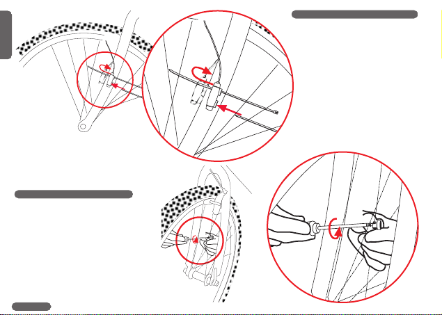
2. Mounting the speed transmitter
The sensor should be mounted on the
same side of the fork as the holder is
on the handlebar.
Watch out: Do not tighten the cable
ties yet! Accurately position the spoke
magnet and the sensor first, then
tighten the cable ties.
3. Mounting the spoke magnet
Distance between magnet and
sensor should be approx. 1-5 mm.

1-5mm
1-5mm
1.LOCK 2.CLICK
1.PRESS
2.UNLOCK
LOCK
UNLOCK
GB
C
15
3
In case this distance is not
achievable in the current positioning,
slide the sensor and the magnet on
the fork or spoke accordingly.
4. Twist-Click mounting of computer onto holder
The Twist-Click mounting has been exclusively developed for the new line of VDO
CYTEC computers. The computerhead is put onto the handlebar and by a right turn
of the computerhead (TWIST) fixed to the holder (CLICK).
It is just as easy to remove the computerhead from the handlebar holder.
Slightly push the computerhead down, twist it to the left, remove computerhead from
handlebar holder.

OPEN CLOSE
GB
C
15
4
5. Installing battery into computer head
To save battery power, your VDO CYTEC comes with the battery not yet fitted. Prior to initial use you have to install the battery first.
If you find the computer is not functioning properly after a battery change, push the AC-button (Auto Clear) on the rear side of the
computer to reset.

GB
C
15
5
6. Information features of your VDO CYTEC C 15
Your VDO CYTEC C 15 provides you with following information:
KMH-MPH current speed indicated in either KMH or MPH, featuring automatic conversion into MPH
TRP trip counter, counts your trip distance up to 999,99 km or miles.
RID trip timer, keeps track of the actual riding time featuring automatic start/stop function, up to 9:59:59 (hrs:min:sec)
STP manual stop watch, counting up to 9:59:59 (hrs:min:sec)
AVS average speed, accurate to two decimal points
MAX maximum speed, achieved during a ride, accurate to two decimal points
permanent comparison of current and average speed. Deviations are indicated by up/down arrows in the display
TCNT Second trip counter featuring a preset mode, intended for use while following road-book instructions.
CLK clock with 12 h or 24 h selectable display mode
TOT total riding time, adding up all riding times of individual rides RID. Resetable to zero individually, i.e. per month, per
week etc.
ODO 1 odometer 1, counting distances ridden on bicycle 1, (wheelsize 1) up to 99,999 KM or M
ODO 2 odometer 2, counting distances ridden on bicycle 2, (wheelsize 2) up to 99,999 KM or M
TOTODO total odometer, adding up values of odometers 1and 2, revealing your total distance traveled on both bikes up to
99,999 KM or M
FRE FREEZE-mode, the frame at passing the finish line becomes "frozen" and further impulses are not indicated. Your
freeze-frame data can be read back from memory later
WS 1+WS 2 two wheelsizes for two different bicycles selectable

Function
TRP
RID
AVS
STP
MAX
Mode 1
Function
TCNT
CLK
TOT
ODO1
ODO2
TOTODO
Mode 2
SS
Function
STP-Start/Stop
GB
C
15
6
7. Operating your VDO CYTEC C 15
Button / Key Covering
Your VDO CYTEC C 15 has 3buttons / keys
Mode 1, Mode 2 and SS

GB
C
15
7
These buttons / keys have several functions.
All functions of the respective buttons / keys outlined in the following chart below.
Your display in Button / Key Length of What is going on?
dicates following to be pushed pushing the
information button / key
TRP-AVS-RID- MODE 1 brief (0.1 sec) next information from MODE 1 is indicated
STP-MAX
TCNT-CLK-TOT- MODE 1 brief (0.1 sec) computer changes display information from MODE 2 data to
ODO1-ODO2- TRP-data of MODE 1
TOTODO
TRP-AVS-RID MODE 1 normal (1.5 sec) TRP-AVS-RID are automatically rotated, one at a time displayed
for 1.5 sec.
TRP MODE 1 long (5 sec) enter set-up mode for wheelsizes
CLK MODE 1 long (5 sec) enter set-up mode for clock is
ODO 1-ODO 2 MODE 1 long (5 sec) enter set-up mode for odometers
RID-AVS-STP-MAX MODE 1 long (5 sec) switching from wheelsize 1 to wheelsize 2 and vice-versa
TCNT MODE 1 long (5 sec.) Set-up mode for TCNT (second trip counter) is called into display
TCNT-CLK-TOT- MODE 2 brief (0.1 sec) next information from MODE 2 is indicated
ODO1-ODO2-
TOTODO
TRP-AVS-RID- MODE 2 brief (0.1 sec) computer changes display information from MODE 1 data to
STP-MAX MODE 2 data. TCNT always being the first information indicated
TRP-AVS-RID-MAX MODE 2 long (5 sec) TRP-AVS-RID-MAX information reset to zero.
TCNT MODE 2 long (5 sec.) Second trip counter TCNT is being reset to zero
TOT MODE 2 long (5 sec) total riding time counter reset to zero
STP MODE 2 long (5 sec) stop watch STP reset to zero
any of the following MODE 1 brief (0.1 sec) FREEZE function either activated or deactivated, computer either
information: + stops or picks up functioning in regular modes.
TRP-AVS-RID-STP- MODE 2
MAX-TCNT-CLK-
TOT-ODO1-ODO2-
TOTODO
STP SS brief (0.1 sec) either start or stop run of stop watch

SCROLL
Press MODE 1 1,5 sec.
Start Scroll
Press MODE 2 5sec.
Reset
GB
C
15
8
8. Scroll function
To provide any information at a glance, your VDO CYTEC C 15 features
a scroll function. Calling up the scroll function automatically displays
information for a period of 1.5 sec. Scroll function may be called upon if any
of the following information is on display: TRP-AVS-RID. Scroll function is
activated by pressing the MODE 1 button for 1.5 sec.
9. Second trip counter TCNT
Your VDO CYTEC features a second trip counter TCNT. This second trip
counter allows you to easily follow road-book instructions. The TCNT may be
preset to an individual value from which it then counts up. In case you have
missed a turning point in your road-book tour, you may return to the tour leg
where you have gotten lost, re-enter the correct value and keep going from there.
Set-up mode for your second trip counter TCNT
Step 1: Call TCNT information into display.
Step 2: Press MODE 1 key for 3 sec. Display shows "TCNT" and a flashing number.
Step 3: By pressing MODE 2 key, the number can be changed.
Step 4: By pressing MODE1 key you proceed to the next number, which you can
change by pressing MODE 2 key.
Step 5: Once you have entered the last number for your TCNT, exit set-up mode by
pressing MODE 1 key for 3 sec..
Watch out: When you exit set-up without having completed entering your data, the
computer may well work with faulty values leading to misinformation in
your display.
Reset TCNT to zero
The second trip counter TCNT is reset to zero by pressing MODE 2 key for 5 sec. Before resetting to zero, make sure that TCNT
information is called into display.
Watch out: Pressing the MODE 2 key for 5 sec. without TCNT data being displayed probably resets your TRP-RID-AVS-MAX
data to zero.
Table of contents
Other VDO CYTEC Bicycle Accessories manuals


