v.LOGiC V5-CIC-E-PNP User manual

Version 26.11.2019 V5-CIC-E-PNP
v.LOGiC Intelligent Solution
Interface
V5-CIC-E-PNP
Compatible with the E-series BMW and Mini with
navigation system or radio and 6.5” or 8.8”
monitor with 4pin HSD LVDS connector

Version 26.11.2019 V5-CIC-E-PNP
Page1"
Product features
• Own on-screen display and setup
• Rear-view camera input
• Automatic switching to rear-view camera input on engagement of reverse gear from
all operation modes
• Front camera input / SMART-LINK input
• Control of SMART-LINK module over iDrive control panel
• Manual switching to rear-view camera (only for vehicles with PDC button)
• Manual return from rear-view and front camera (cancellation of automatic switching)
• 2 trigger outputs (+12V max. 1A), separately adjustable switching events (CAN, ACC,
camera, reverse gear)
• Picture-in-picture mode combining after-market rear-view and front camera
picture(s) with factory parking sensor graphics
• Compatible with all factory video accessories (e.g. rear-view camera, Top-View,
nightvison, DVD-changer, TV-tuner)
• USB update-port for software-updates by consumer

Version 26.11.2019 V5-CIC-E-PNP
Page2"
Contents
1. Prior to Installation
1.1. Delivery contents
1.2. Check compatibility of vehicle and accessories
1.3. Setting the dip switches of the interface-box V5C-M636
1.4. LED’s of the interface-box V5C-M636
2. Connection schema
3. Installation
3.1. Connecting interface-box and harnesses
3.2. LVDS connection
3.2.1. After-market front camera
3.2.1.1. Connection to the after-market front camera
3.2.1.2. Settings for connecting an after-market front camera
3.2.2. After-market rear-view camera
3.2.2.1. Connection to the after-market rear-view camera
3.2.2.2. Settings for connecting an after-market rear-view camera
3.2.2.3. Settings for OEM rear-view camera
3.2.3. SMART-LINK
3.2.3.1. SMART-LINK video and control connection
3.2.3.2. SMART-LINK audio connection
3.2.3.3. Settings for SMART-LINK connecting
3.2.4. Configurable trigger outputs
3.3. Picture settings
3.4. Picture format settings
4. Operation
4.1. OSD – On-screen display
4.1.1. OSD – Operation
4.1.1.1. 8-button iDrive
4.1.1.2. 2-button iDrive in Mini
4.1.2. OSD – Additional setting options
4.2. Video-in-motion function
4.3. Selecting the interface as current video-source
4.4. Controlling of the connected SMART-LINK module
5. Specifications
6. Connections (interface-box)
7. Technical support

Version 26.11.2019 V5-CIC-E-PNP
Page3"
Legal Information
By law, watching moving pictures while driving is prohibited, the driver must not be
distracted. We do not accept any liability for material damage or personal injury resulting,
directly or indirectly, from installation or operation of this product. This product should only
be used while standing or to display fixed menus or rear-view-camera video when the
vehicle is moving, for example the MP3 menu for DVD upgrades.
Changes/updates of the vehicle’s software can cause malfunctions of the interface. We
offer free software-updates for our interfaces for one year after purchase. To receive a free
update, the interface must be sent in at own cost. Labor cost for and other expenses
involved with the software-updates will not be refunded.

Version 26.11.2019 V5-CIC-E-PNP
Page4"
1. Prior to installation
Read the manual prior to installation. Technical knowledge is necessary for installation. The
place of installation must be free of moisture and away from heat sources.
1.1. Delivery contents
1.2. Check compatibility of vehicle and accessories
Requirements
Navigation E-series and Mini with navigation system or radio with 6.5” or 8.8“
monitor (E-series) with 4pin HSD LVDS connector
Interface-box
V5C-M636
HW_____ SW_____
Take down the SW-version and HW-version of the interface boxes, and store this
manual for support purposes.
V5C-UNI01
harness
LVDS cable
CAB-HSD-MG060-OZ
LVDS cable
CAB-HSD-DD075-O
TV-BM01
harness
Version 26.11.2019 V5-CIC-E-PNP
Page5"
1.3. Setting the dip switches of the interface-box V5C-M636
Dip 1 and 2 on the back of the interface-box V5C-M636 are used to set the monitor type. The
default setting is:
Vehicle/ navigation
Dip 1
Dip 2
Dip 3
CIC-E (E-series), 6.5“ monitor – version 1
OFF
OFF
OFF
CIC-E (E-series), 6.5“ monitor – version 2
ON
OFF
ON
CIC-E (E-series), 8.8“ monitor
OFF
ON
OFF
After each change of the dip switch settings you have to execute a power reset of the
interface-box!
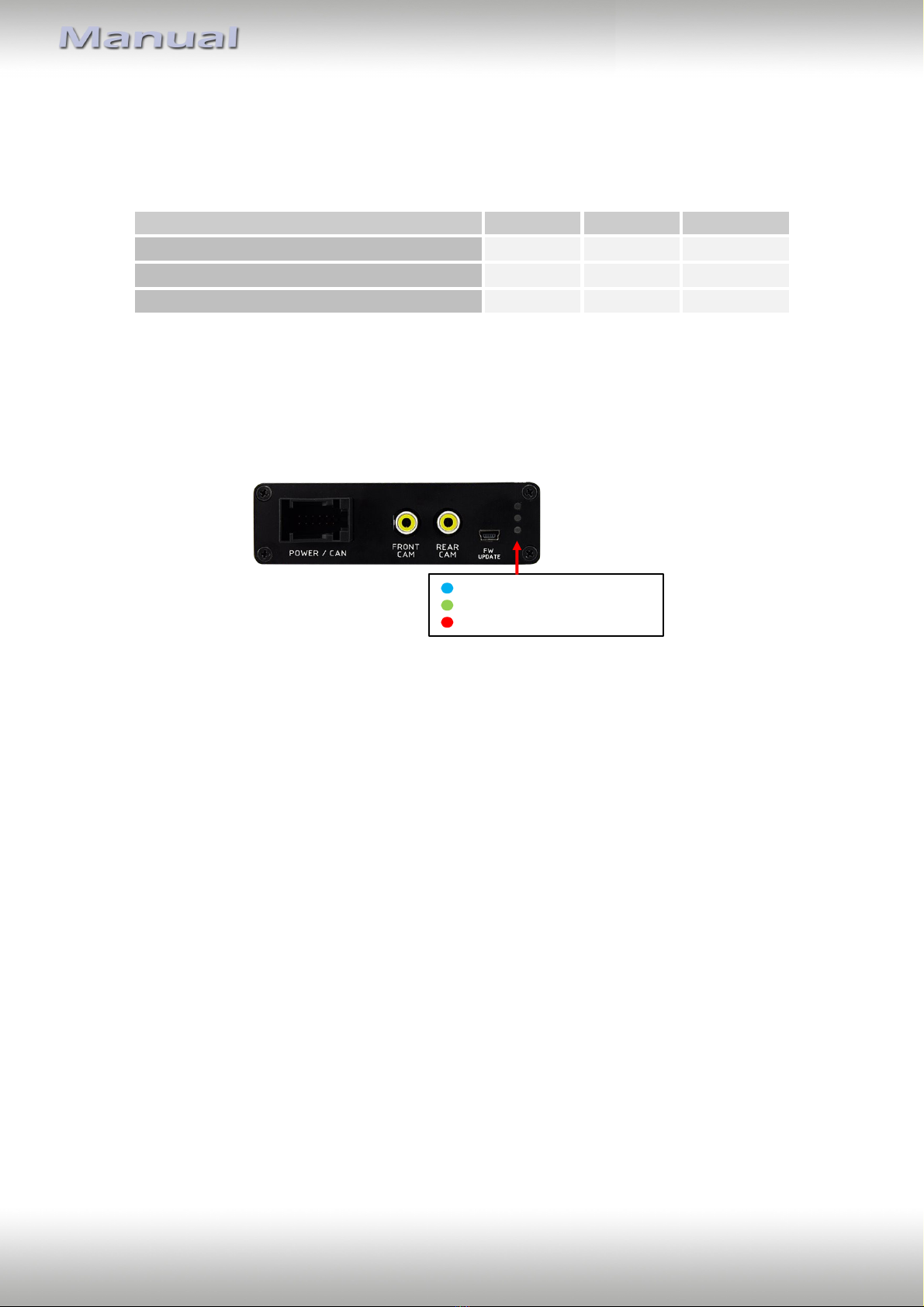
1.4. LED‘s of the interface-box V5C-M636
Valid%input source
CAN%ok
Power

Version 26.11.2019 V5-CIC-E-PNP
Page6"
2. Connection schema

Version 26.11.2019 V5-CIC-E-PNP
Page7"
3. Installation
Switch off ignition and disconnect the vehicle’s battery! The interface needs a permanent
12V source. If according to factory rules disconnecting the battery is to be avoided, it is
usually sufficient to put the vehicle is sleep-mode. In case the sleep-mode does not show
success, disconnect the battery with a resistor lead.
If power source is not taken directly from the battery, the connection has to be checked
for being start-up proven and permanent.
Prior to wire and device installation we suggest to connect and test correct function of all
after-market and factory infotainment equipment!
The interface is installed on the backside of the head unit.
3.1. Connecting interface-box and harnesses
Remove the female Quadlock connector of the vehicle harness from the rear of the
navigation computer.
Remove optical leads from the female Quadlock connector of the vehicle harness and
insert them into the female Quadlock connector of harness TV-BM01 at the same
position.
Connect female Quadlock connector of vehicle harness to the male Quadlock
connector of harness TV-BM01.
Connect female Quadlock connector of harness TV-BM01 to the male Quadlock
connector of the navigation computer
1
2
3
4

Version 26.11.2019 V5-CIC-E-PNP
Page8"
Connect female 8 pin molex connector of the harness TV-BM01 to the
male 8 pin molex connector of the harness TV-BM01.
Connect female 12pin AMP connector of the harness TV-BM01 to the
front site of the V5C-M636 interface box.
3.2. LVDS connection
Connect the female 4pin HSD LVDS connector of the LVDS cable CAB-HSD-DD075-O
to the male 4pin HSD LVDS connector (LVDS-IN) on the rear of the
interface-box V5C-M636.
Remove the pink female 4pin HSD LVDS connector of the vehicle harness at the back
of the head unit and connect it to the male 4pin HSD LVDS of the
CAB-HSD-MG060-OZ LVDS cable.
Connect the female 4pin HSD LVDS connector of the LVDS cable CAB-HSD-MG060-OZ
to the male 4pin HSD LVDS connector (LVDS-OUT) on the rear of the
interface-box V5C-M636.
Connect the female 4pin HSD LVDS connector of the LVDS cable CAB-HSD-DD075-O
to the pink male 4pin HSD LVDS connector on the rear of the head unit.
5
6
1
2
3
4

Version 26.11.2019 V5-CIC-E-PNP
Page9"
3.2.1. After-market front camera
3.2.1.1. Connection to the after-market front camera
Connect the video RCA of the after-market front camera to the female RCA connector
“FRONT CAM” of the interface box V5C-M636.
- The pink wire of harness V5C-UNI01 can be used
for +12V electric power supply (max. 1A) of the
after-market front camera. Configure in the OSD-
menu “MISC”, menu item “POWER OUT 2” the
designated electric power supply (see chapter
“Configurable switching outputs”).
-
Inte rface)box
V5C)M636
FRONT
Front8camera
+12 V8camera
power
V5C)UNI018
harness
Power&Out&1&(max.&1A)
1
2
1
2
Table of contents
Other v.LOGiC Automobile Accessories manuals


