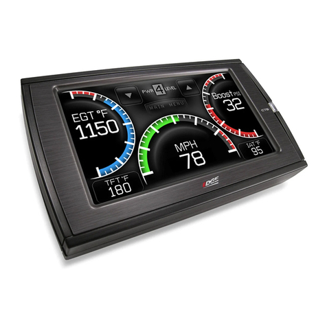
Ubiqconn VT1020 User manual


1
Contents
CONTENTS ....................................................................................................................................................................... 1
SAFETY PRECAUTIONS ................................................................................................................................................ 4
REGULATORY AND CERTIFICATION ........................................................................................................................ 6
FCC ..................................................................................................................................................................................................... 6
CE MARKING..................................................................................................................................................................................... 7
R&TTE .............................................................................................................................................................................................. 7
LITHIUM BATTERY SAFETY STATEMENT ...................................................................................................................................... 7
CHAPTER 1. PRODUCT INTRODUCTION ............................................................................................................... 8
HARDWARE SPECIFICATIONS ......................................................................................................................................................... 8
OPERATING SYSTEM SUPPORT ....................................................................................................................................................... 9
ENVIRONMENT ................................................................................................................................................................................. 9
I/O PORTS ...................................................................................................................................................................................... 10
DIMENSION AND WEIGHT ........................................................................................................................................................... 11
PACKAGE LIST ................................................................................................................................................................................ 12
CHAPTER 2. HARDWARE INSTALLATION ............................................................................................................ 13
RAM MODULE ............................................................................................................................................................................... 13
Installing/Removing a RAM Module .................................................................................................................................... 13
SSD MODULE ................................................................................................................................................................................. 15
Installing an SSD Module ........................................................................................................................................................... 15
Removing an SSD Module .......................................................................................................................................................... 17
INSTALLING/REMOVING THE MINI-PCIE CARDS ..................................................................................................................... 18
INSTALLING/REMOVING THE WWAN MODULE ...................................................................................................................... 19
INSTALLING/REMOVING THE SIM CARD ................................................................................................................................... 20
INSTALLING ANTENNAS ............................................................................................................................................................... 20
CHAPTER 3. HARDWARE MOUNTING................................................................................................................... 22
VESA 100 Mounting Option ...................................................................................................................................................... 22
VESA 75 Mounting Option ......................................................................................................................................................... 22
CHAPTER 4. START UP ............................................................................................................................................... 23
POWERING THE SYSTEM .............................................................................................................................................................. 23

2
Starting Up the System ............................................................................................................................................................... 23
Powering Down the System ...................................................................................................................................................... 23
BRIGHTNESS AND DIMMING CONTROL...................................................................................................................................... 23
LED STATUS ................................................................................................................................................................................... 24
DEFROST/DEFOG OPTION ........................................................................................................................................................... 24
Enabling Defrost Function ........................................................................................................................................................ 24
Enabling Defog Function ........................................................................................................................................................... 25
CALIBRATING THE TOUCH SCREEN ............................................................................................................................................ 25
VT1020 CONFIGURATION OPTIONS ......................................................................................................................................... 26
CHAPTER 5. JUMPERS AND CONNECTORS .......................................................................................................... 28
EXTERNAL CONNECTORS PIN ASSIGNMENTS ........................................................................................................................... 28
DIO Port ............................................................................................................................................................................................. 28
RS-232 Port (COM1)..................................................................................................................................................................... 29
CAN BUS Ports ................................................................................................................................................................................ 30
Expansion Port ............................................................................................................................................................................... 31
USB Port ............................................................................................................................................................................................ 32
Power Connector ........................................................................................................................................................................... 33
INTERNAL CONNECTORS PIN ASSIGNMENT .............................................................................................................................. 34
Power Connector ........................................................................................................................................................................... 34
LED Connector ................................................................................................................................................................................ 35
Resistive Touch Screen Connector ......................................................................................................................................... 35
GPS Connector ................................................................................................................................................................................ 36
Battery Connector ......................................................................................................................................................................... 36
Power Input Voltage .................................................................................................................................................................... 37
Internal Battery Source Setting ............................................................................................................................................. 37
CHAPTER 6. UPANEL SETTING ................................................................................................................................ 38
DEVICE INFORMATION ................................................................................................................................................................. 39
VEHICLE STATUS ........................................................................................................................................................................... 40
COMMUNICATION SETTING ......................................................................................................................................................... 41
Power On/Off WWAN Module ................................................................................................................................................. 41
WWAN Communication Setting ............................................................................................................................................. 42
SYSTEM STATUS & SETTING ........................................................................................................................................................ 43
Power Management Setup ........................................................................................................................................................ 44
Wake up Setting ............................................................................................................................................................................. 50

3
I/O Configuration .......................................................................................................................................................................... 53
Brightness Setting ......................................................................................................................................................................... 53
Watchdog Timer ............................................................................................................................................................................ 54
Programmable Button ................................................................................................................................................................ 56
LOCATION AND SENSOR ............................................................................................................................................................... 59
Enable/ Disable GPS Receiver ................................................................................................................................................. 61
Serial Port Setting ......................................................................................................................................................................... 62
Baud Rate Setting ......................................................................................................................................................................... 62
CHAPTER 7. MAIN BIOS SETTING .......................................................................................................................... 64
SET BOOT SEQUENCE ................................................................................................................................................................... 64
SET THE SYSTEM CONFIGURATION ............................................................................................................................................. 65
Setting the System Date ............................................................................................................................................................. 65
Setting the System Time ............................................................................................................................................................. 65
SYSTEM INFORMATION ................................................................................................................................................................. 66
BOOT FEATURES ............................................................................................................................................................................ 66
NETWORK STACK .......................................................................................................................................................................... 67
ENABLE/ DISABLE SYSTEM COMPONENTS ............................................................................................................................... 67
ACCOUNT’S PASSWORD SETTING ................................................................................................................................................ 68
HDD SECURITY SETTING ............................................................................................................................................................. 69

4
Safety Precautions
1. Read these safety instructions carefully.
2. Keep this user’s manual for later reference.
3. Disconnect this equipment from any AC outlet before cleaning. Use a damp cloth. Do not
use liquid or spray detergents for cleaning.
4. For plug-in equipment, the power outlet socket must be located near the equipment and
must be easily accessible.
5. Keep this equipment away from humidity.
6. Put this equipment on a stable surface during installation. Dropping it or letting it fall may
cause damage.
7. Do not leave this equipment in either an unconditioned environment or in an above 40oC
storage temperature as this may damage the equipment.
8. The openings on the enclosure are for air convection to protect the equipment from
overheating. DO NOT COVER THE OPENINGS.
9. Make sure the voltage of the power source is correct before connecting the equipment to
the power outlet.
10. Place the power cord in a way so that people will not step on it. Do not place anything on
top of the power cord. Use a power cord that has been approved for use with the product
and that it matches the voltage and current marked on the product’s electrical range label.
The voltage and current rating of the cord must be greater than the volt- age and current
rating marked on the product.
11. All cautions and warnings on the equipment should be noted.
12. If the equipment is not used for a long time, disconnect it from the power source to avoid
damage by transient overvoltage.
13. Never pour any liquid into an opening. This may cause fire or electrical shock.
14. Never open the equipment. For safety reasons, the equipment should be opened only by
qualified service personnel.
15. If one of the following situations arises, get the equipment checked by service personnel:
a. The power cord or plug is damaged.
b. Liquid has penetrated into the equipment.
c. The equipment has been exposed to moisture.
d. The equipment does not work well, or you cannot get it to work according to the user’s

5
manual.
e. The equipment has been dropped and damaged.
f. f. The equipment has obvious signs of breakage.
16. Do not place heavy objects on the equipment.
17. The unit uses a three-wire ground cable which is equipped with a third pin to ground the
unit and prevent electric shock. Do not defeat the purpose of this pin. If your outlet does
not support this kind of plug, contact your electrician to replace your obsolete outlet.
18. CAUTION: DANGER OF EXPLOSION IF BATTERY IS INCORRECTLY RE- PLACED. REPLACE
ONLY WITH THE SAME OR EQUIVALENT TYPE REC- OMMENDED BY THE
MANUFACTURER. DISCARD USED BATTERIES ACCORDING TO THE MANUFACTURER’S
INSTRUCTIONS.

6
Regulatory and Certification
FCC
This device complies with Part 15 of the FCC Rules. Operation is subject to the following two
conditions:
1. This device may not cause harmful interference.
2. This device must accept any interference received, including interference that may cause
undesired operation.
This equipment has been tested and found to comply with the limits for a Class B digital device,
pursuant to Part 15 of the FCC Rules. These limits are designed to provide reasonable
protection against harmful interference in a residential installation. This equipment generates,
uses, and can radiate radio frequency energy and, if not installed and used in accordance with
the instructions, may cause harmful interference to radio communications. However, there is
no guarantee that interference will not occur in a particular installation. If this equipment does
cause harmful interference to radio or television reception, which can be determined by
turning the equipment off and on, the user is encouraged to try to correct the interference by
one or more of the following measures:
Reorient or relocate the receiving antenna.
Increase the separation between the equipment and the receiver.
Connect the equipment into an outlet on a circuit different from that to which the
receiver is connected.
Consult the dealer or an experienced radio/TV technician for help.
Shielded interconnect cables and shielded AC power cable must be employed with this
equipment to insure compliance with the pertinent RF emission limits governing this device.
Changes or modifications not expressly approved by the system’s manufacturer could void the
user’s authority to operate the equipment.
Any changes or modifications not expressly approved by the party responsible for
compliance could void the user’s authority to operate the equipment.
This device is operation in 5.15 – 5.25GHz frequency range, then restricted in

7
indoor use only, Outdoor operations in the 5.15 – 5.25GHz is prohibit.
.
CE Marking
This product has passed the CE test for environmental specifications when shielded cables are
used for external wiring. We recommend the use of shielded cables. Please contact your local
representative for ordering information.
This product has passed the CE test for environmental specifications. Test conditions for
passing included the equipment being operated within an industrial enclosure. In order to
protect the product from being damaged by ESD (Electrostatic Discharge) and EMI leakage, we
strongly recommend the use of CE-compliant industrial enclosure products.
R&TTE
This device complies with the essential requirements of the R&TTE Directive 1999/5/EC.
Lithium Battery Safety Statement
Lithium battery inside. Danger of explosion if battery is incorrectly replaced. Replace only with
same or equivalent type recommended by battery manufacturer.
THIS PRODUCT CONTAINS LITHIUM-ION BATTERY PACKS. IT MUST BE DISPOSED
OF PROPERLY. CONTACT LOCAL ENVIRONMENTAL AGENCIES FOR INFORMATION
ON RECYCLING AND DISPOSAL PLANS IN YOUR AREA.

8
Chapter 1. Product Introduction
VT1020 is the ultra-rugged in-vehicle terminal with 10.4” high brightness display, is designed
for the construction, mining, logistics application.
With IP66 protection rating, wide temperature design, wide power range input, and rich
expanding interfaces supporting in-vehicle connectivity, VT1020 is a well thought-out
in-vehicle device suitable to overcome the demanding challenge.
Hardware Specifications
Item
Description
Processor
Intel® Bay Trail-I E3845 1.91GHz (Quad Core)
Memory
4GB SO-DIMM DDR3L SDRAM, up to 8GB
Storage
SSD x 1, SD slot x 1
Display
10.4-inch XGA (1024 x 768); 70,000 hours backlight life
1,000 nits sunlight readable to 0.1 nits hyper dimming for night
mode operation
Viewing angel: 140(H)/ 120(V) (CR>10)
Anti-reflection tempered 5-wire resistive touch panel
PCT (Gorilla) by request only
Touch Panel
5-wire Resistive Touch Screen
Defrost/Defog function (Option)
Wireless
Connectivity
802.11 ac/a/b/g/n 2x2
Bluetooth 4.0 + HS
GPS / QZSS or GLONASS
1 mini PCIe slot (full size) for cellular module
External RP-SMA connectors for wireless expansion (WiFi/WWAN),
SMB for GPS
Item
Description
Power Input
VT1020-HR : 18-60VDC 4.5A
VT1020-HRD: 18-60VDC 4.5A
VT1020-LR: 9-32VDC 9A

9
VT1020-LRD: 9-32VDC 9A
Battery
2,900mAh, 7.5V
Housing
(Mechanical)
Die-cast aluminum alloy, fanless design
Video Capturing
Optional video input up to 4 ports with comprehensive SDK included
Certification
CE, FCC, CB
Operating System Support
Windows 7 Professional with Service Pack 1 x64
Windows Embedded 8.1 Industry x64
Windows Embedded 8 Standard x64
Windows Embedded Standard 7 x64
Linux Kernel Version 3.19
Environment
Operating temperature:
-30°C (-22°F) to 55°C (122°F)
In accordance with MIL-STD-810G Method 501.5 High Temperature Procedure II –
Operation
In accordance with MIL-STD-810G Method 502.5 Low Temperature Procedure II –
Operation
Storage temperature:
-30°C (-22°F) to 70 °C (158°F)
In accordance with MIL-STD-810G Method 501.5 High Temperature Procedure I –
Storage
In accordance with MIL-STD-810G Method 502.5 Low Temperature Procedure I –
Storage
Relative humidity:5% to 95% @ 30°C (86°F) to 60°C (140°F) non-condensating in
accordance with MIL-STD-810G Method 507.5 Humidity Procedure II Aggravated Cycles
Vibration Test:
Table of contents
Popular Touchscreen manuals by other brands

Elecro Engineering
Elecro Engineering Poolsmart Plus Installation & operating manual

Johnson Controls
Johnson Controls IQ4 HUB installation manual

Elo TouchSystems
Elo TouchSystems ET2270L user manual

Elo TouchSystems
Elo TouchSystems ET1002L user manual

Elo TouchSystems
Elo TouchSystems 3201L user manual

Duratec
Duratec S15 user manual