TechnicalTechnical
ServiceService
ManualManual
System
Components
System
Components
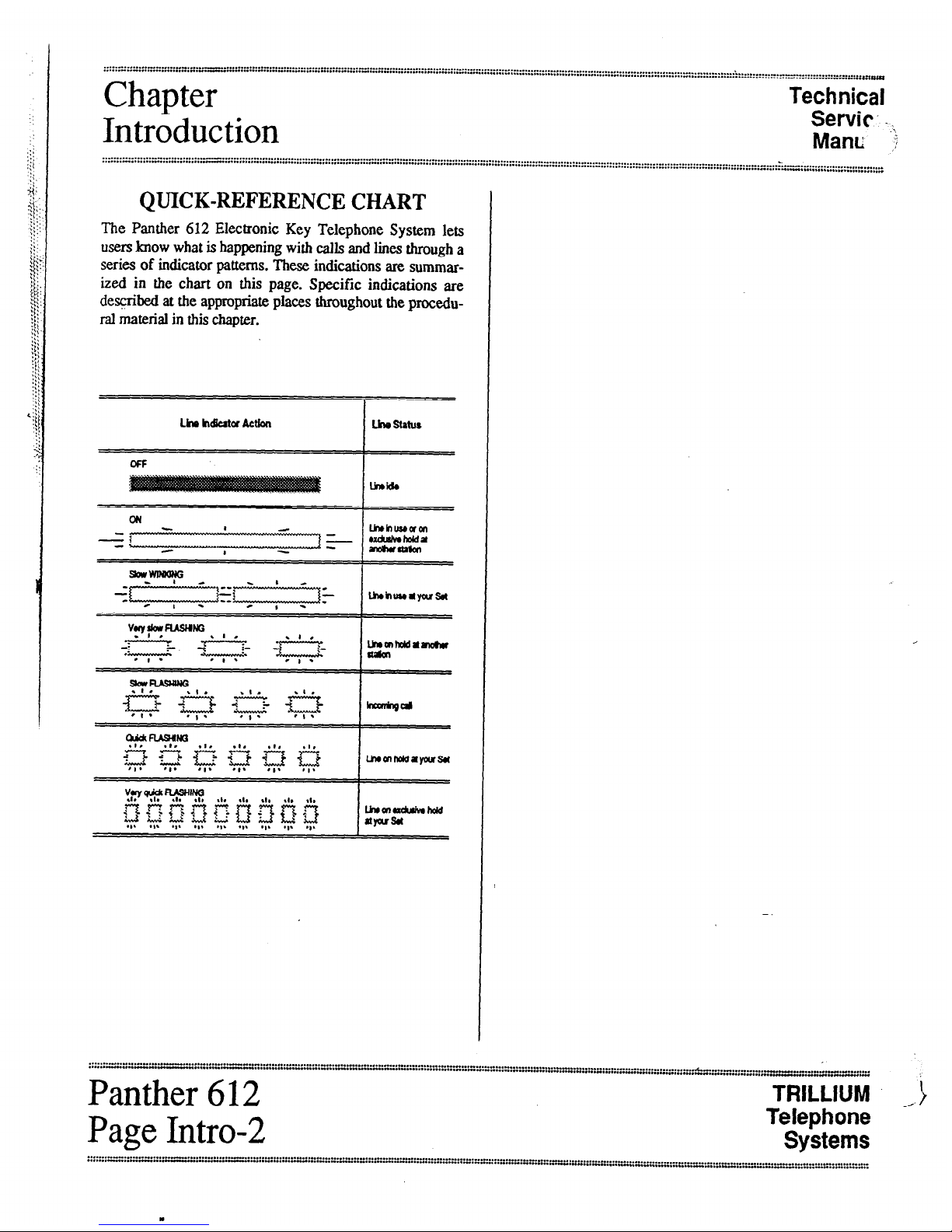
STANDARD COMPONENTS
OneKey ServiceUnit (KSU)
Part Number 90-0166(tone only)
or
Part Number 90-0084(tone/rotary
The ~onelrotary key service unit (KSU) for the Panther 612
Electronic Key Telephone System can be programmed to
operate with either dual-tone, multi-frequency (DTMF) or
rotary (pulse) signaling. The signaling on each Central
< Office (CO) line can be programmed independently. The
tom only KSU operates only with DTMF signaling. Other
than signaling differences, both KSU models look alike and
operate identically.
The KSU has three connectors on its left side (labeled
C01.2, C03.4, and CO%) to attach the six incoming tele-
phone company (telco) CO lines - one connector for each
pair of lines (line 6 must be left vacant if the optional Door
Answer Unit is installed). Also on the left side of the KSU
are connectors labeled DOOR (used for the optional Door
/- Answer Unit), PAGE (used for external paging equipment),
MUSIC (used for an external background and on-hold music
source). POWER FALL (used for the optional Power Fail
Transfer Unit).
Next, the KSU has one recessed light-emitting diode (LED)
indicator (labeled STATUS), four miniature dual in-line
package (DIP) switches (labeled, from top to bottom, 1
PROGRAM [used to return features to their default, factory
preprogrammed conditions], 2 PROGRAM [used to pro-
gram system features], 3 [not used], and 4 BATTERY [used
to save feature programming]), and one recessed pushbutton
(labeled RESET).
Near the bottom left of the KSU is a 50-pin connector, la-
beled STATIONS 10 TO 21/LOUD BELL, that is used to
connect the KSU to the station wiring main distribution
frame (MIX) - and, through the MDF, to alI the system
stations. The last pair is also optionally available for con-
necting an external loud bell or other sounding device
through an external dry contact interface unit.
On the bottom of the KSU is a connector labeled SMDR
(used for the optional SMDR Interface unit).
The KSUs power cord (at the top of the KSU) plugs into a
110 V ac outlet (but only at the appnpriate time; see the
Connection Procedures section). A grounding wire (12
AWG, solid copper) which connects to the top of the KSU
must be attached to a ground clamp, umally on a water pipe.
An input connector (labeled EXTERxti BATTERY) for
an optional 24 V backup battery is aha provided at the top
of the KSU. If ac power is lost, the switchover to backup
battery power is automatic when the qcional backup battery
is connected.
The unit comes with 4 screws for mmting the KSU on a
backboard
Up to Twelve Telephonetits
Part Number 90-0266
(non-handsfree)
&t Number 90-0168
(handsfreewith busylamp field)
Other than the handsfree operation and the busy lamp field,
these two models look alike and operaa: identicatly. For ex-
ample, both have an attractive black marretIni&.
Each Set’sbase has twelve dual-functkm statiort select/speed
call keys (labeled 10 through 21- tix top key is also used
for last number
Redial),sixline
seleukeys (labeled 1,2,3.
4,5, and 6), seven dedicated functim keys (labeled
Hold,
Flash/Cancel, Conference, Intercom, Speed,
Speaker,andMic.on/off) and
a tone d&l keypad
The line
1,2,3,4,5,
and 6 keys, the
Uercom key,
and the
Mic.on/off key
have accompanying szus indicators. And,
only on handsfreebusy lamp field (HFELF) Sets, each sta-
tion select key (10 through
21)
also has an accompanying
status indicator.
Finally, the base has a speaker volume control (a sliding ad-
justment) and a ringer control switch (a ‘J-position switch,
for low, medium, and high volume riqing).
Each Setalso includes a telephone hardset and two modular
cords - a4-conductor, coiled cord fa connecting the hand-
set to the Set, and a 4-conducur modular cord for
connecting the Set to the station wiring jack.
=:=:I” :::::::::::. x:; :::::::: ;:r< ::::::::::::::::::; ::::::::::::: ~‘::.w’“-“:“:~“:::..- . . . . . . . . . . . . . . . . . . . . . . . . . . . . . . . . . . . . . . . . . . . . . . . . . . . . . . . . . . . . . . . . . . . . . . . . . . . . . . ..-...........................
. . . . . ...” . . . . . . . . . . . . “... . . . . . . . . . . . . . . . . . . . . . ...” . . . . . . . . . . . . . . . . . . . . . . . . . . . . . . . . . * . . . . . -..- ._............... I
..” . . . . . . . . . . . . . . --.....“*..* . . . . . . . *..
,-
c
TRILLIUM
Telephone
’ Panther 612
Systems
Page B-l