www
.
T
r
a
il
F
X
.
c
o
m
Page 3of 7 Rev 121218
not fully tighten hardware at this time. NOTE: “L” Brackets may require modification for hardware
larger than 8mm or use brackets supplied with light if possible.
b. Attach the light and brackets to the top of the (2) tabs on the back of the Bumper with the included
8mm x 25mm Hex Bolts, (4) 8mm Flat Washers, (2) 8mm Lock Washers and (2) 8mm Hex Nuts,
(Figure 10). Adjust light position and tighten hardware.
c. Follow light manufacturer’s instructions to wire the light to the vehicle’s electrical system once
Bumper has been fully installed.
9. LED light installation at ends of bumper (sold separately.
a. Insert light into opening and up to mounting slots. Check for clearance between front and back of
light. If necessary, remove the screens from the back of the openings, (Figure 11).
b. Follow the light manufacturer’s instructions to attach each light to slot in the top of the light
opening, (Figure 11). NOTE: On two light systems, attach the flood light to the outer slot and the
spot light to the inner slot.
c. Repeat the above steps for passenger side light installation.
d. Follow light manufacturer’s instructions to properly wire the light to the vehicle electrical system.
10. If front license plate is required, attach the License Plate Bracket to the holes in the bumper with the
included (2) 6mm x 20mm Button Head Screws, (4) 6mm Flat Washers and (2) 6mm Nylon Lock
Nuts, (Figure 12). Insert (2) Plastic Plugs into the square holes in the Bracket. Reuse the factory
screws to attach the license plate to the plastic plugs, (Figure 12).
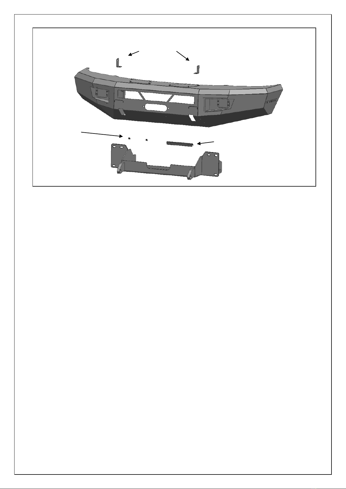
11. With assistance, carefully position the Bumper Assembly up to the ends of the Winch Tray.
Temporarily support the weight of the Bumper. WARNING: To avoid possible injury or damage to the
vehicle, do not proceed until the bumper is fully and safely supported. Models with winch and/or LED
light, check for clearance before fully installing Bumper assembly.
12. Line up the (3) 10mm Studs in the driver side of the Bumper with the (3) holes in the Winch Tray.
Attach the Bumper to the Winch Tray with the included (3) 10mm Flat Washers, (3) 10mm Lock
Washers and (3) 10mm Hex Nuts, (Figures 13 & 14). Do not fully tighten hardware at this time.
Repeat to attach the passenger side of the Bumper to the Winch Tray.
13. Level and adjust the bumper and fully tighten all hardware.
14. Remove covers from top of Bumper for additional access if desired.
15. Do periodic inspections to the installation to make sure that all hardware is secure and tight.
To protect your investment, wax this product after installing. Regular waxing is recommended to add a
protective layer over the finish. Do not use any type of polish or wax that may contain abrasives that could
damage the finish. Mild soap may be used to clean the HD1 Front Bumper assembly.
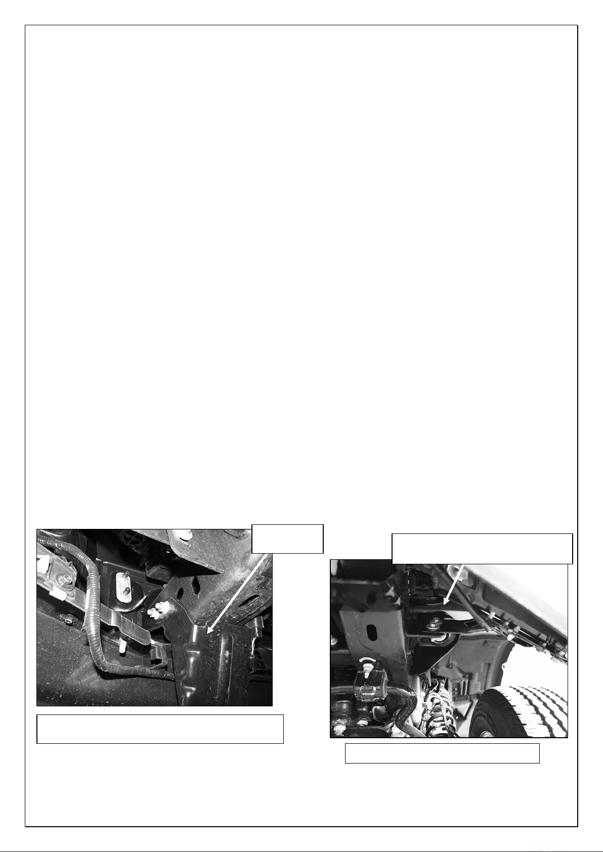
Driver Side Installation Pictured
(Fig 1) Driver side lower frame extension and fog
light wire harness pictured from behind bumper
(Fig 2) Remove outer bumper support
Remove hardware attaching
bumper support brackets to frame