3
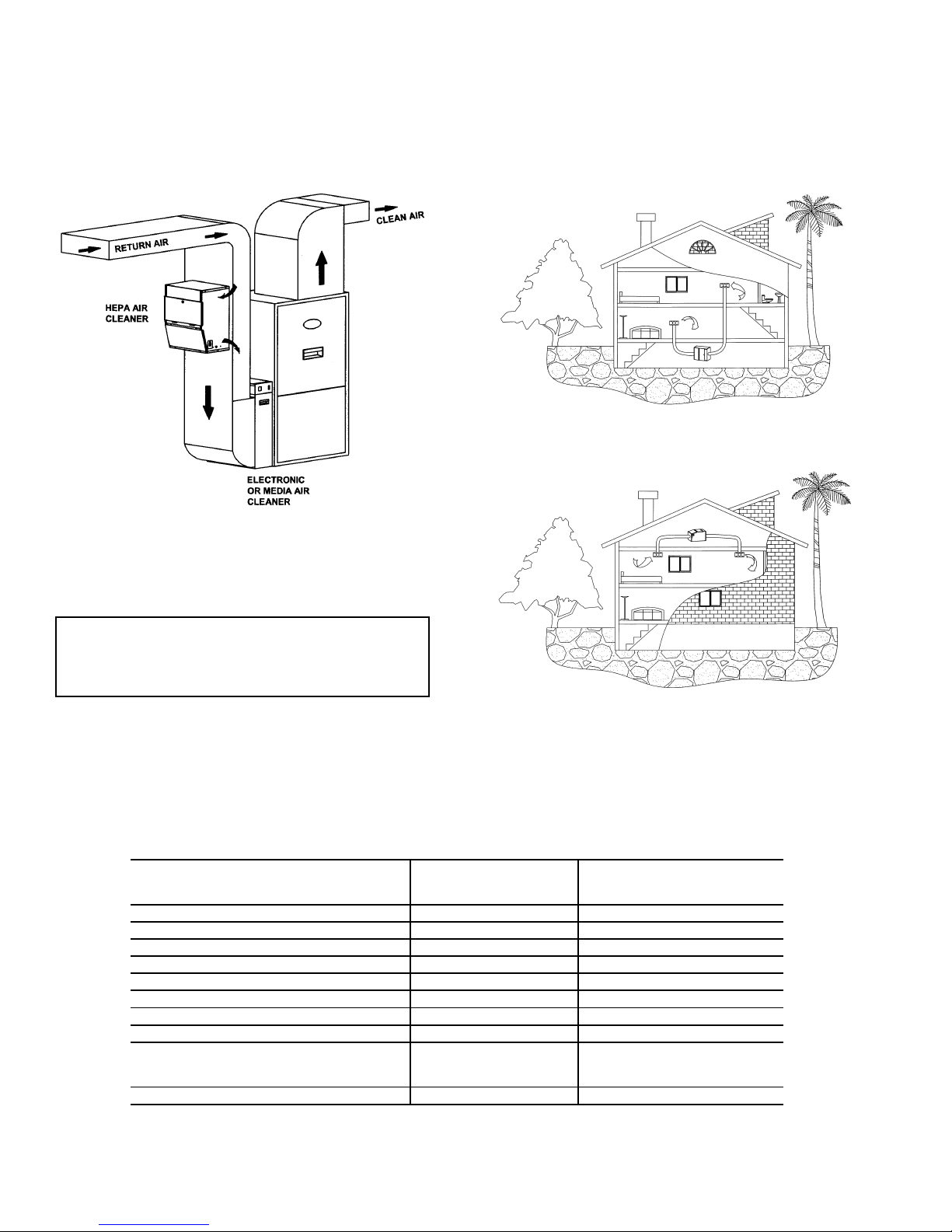
Duct Mount Installation
1. Remove any packaging, as well as the door and filters
before installing. See Maintenance for instructions to
remove the filters.
2. If the unit is to be mounted on the return air plenum, it
must be installed after the last return branch connec-
tion on the plenum. If outside air is introduced into the
return air duct, either through a HRV (Heat Recovery
Ventilator) or directly, it should be added to the system
before the intake inlet to the air cleaner.
3. Tape the mounting template level on the plenum and
cut and drill the necessary holes as marked.
4. Cut the small joints on the mounting flaps on the back
of the unit as indicated. Bend all the flaps outward
slightly less than 90 degrees, except for the upper bot-
tom flap which should be bent up at a 40 degree angle
only. This bottom flap will act as a deflector for the
exhaust air entering back into the plenum.
5. Place the gasket material around the two openings on
the back of the air cleaner. Place the unit on the ple-
num so the flanges are placed through the holes cut in
the duct. Fold all the flanges over, except for the upper
bottom flap, to enclose the duct between the flanges
and the unit. The upper bottom flap should be bent up
at a 40 degree angle only.
6. Secure the unit to the duct with the screws provided.
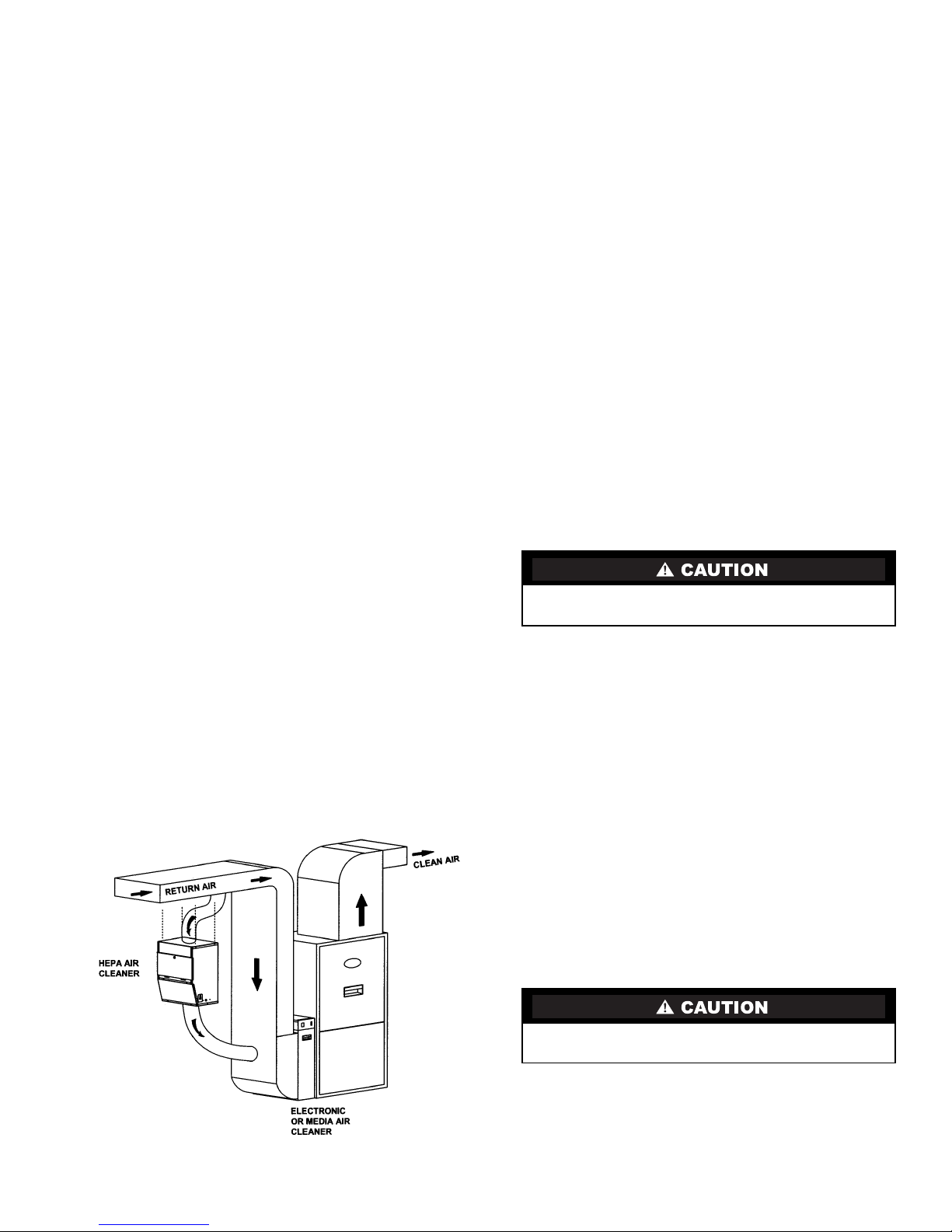
Collar Mount Installation — Inlet collars are available
as a kit from the distributor. See Fig. 5.
1. This unit can be installed with collars and flexible
ducting if desired. Openings are prepunched on the top
and bottom of the unit for this purpose. Remove the
plastic film over the holes and snip out the joints to
open the hole. Do not open the holes in the back of the
unit if the air cleaner is being collar mounted.
2. The collar is installed with the flange on the inside of
the cabinet with only the collar ring on the outside of
the cabinet. Compress the collar until a flange can be
inserted into the opening in the enclosure. Enlarge the
collar to its maximum and install two screws into the
ring to hold it to the proper diameter. Turn the collar in
the hole until the holes in the enclosure line up to the
holes on the collar flange. Secure with the screws
provided.
3. The intake collar on the return duct must be installed
after the last return branch connection on the plenum.
If outside air is introduced into the return air duct,
either through a HRV (Heat Recovery Ventilator) or
directly, it should be added to the system before the
intake inlet to the air cleaner.
4. The 8 in. intake collar (top) must draw air from the
return duct at a location that will be ahead of the clean
exhaust air, that will be returned to the duct from the
air cleaner.
5. An 8 in. collar will be installed on the return duct and
a length of 8 in. flexible hose or duct is required to
attach between the 8 in. intake collar and the collar on
the return duct. When running the hose, make sure that
there are no kinks or sharp bends that will impede the
airflow to the unit. Secure and seal the hose or duct
and connections to prevent air leakage.
6. The 8 in. exhaust collar can be mounted in the same
manner to the bottom of the unit. An 8 in. collar will
be installed on the return duct close to the furnace and
a length of 8 in. flexible hose or duct is required to
attach between the exhaust collar and the collar on the
return duct. The ideal location is low on the return air
boot pointing at the furnace. To prevent air shear
inside the duct, it is recommended that a deflector be
installed inside the boot, so the discharged air is
deflected down into the boot. When running the hose,
make sure that there are no kinks or sharp bends that
will impede the airflow from the unit. Secure and seal
the hose and connections to prevent air leakage.
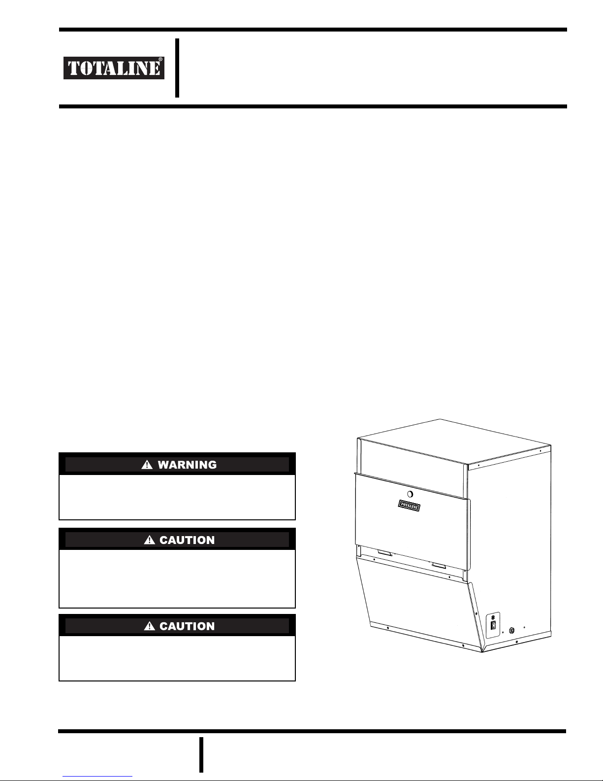
OPERATION
The HEPA air cleaner is designed to run continuously to
provide clean, filtered air 24 hours a day. The fan on the
heating/cooling system, to which the HEPA air cleaner is de-
pendent on for circulated air, should be on ‘continuous’.
NOTE: If the system fan setting is on ‘automatic’, it is recom-
mended that the HEPA air cleaner be operated through an air
switch or relay to turn the air cleaner off when there is no sys-
tem fan on.
The unit plugs into a regular 120 volt outlet and is
controlled by a switch located on the bottom of the unit, near
the cord.
NOTE: Do not place the cord where it might be walked on or
where something might be rolled over the cord.
The door must be secured for the air cleaner to operate. All
filters must be in place for the unit to operate properly.
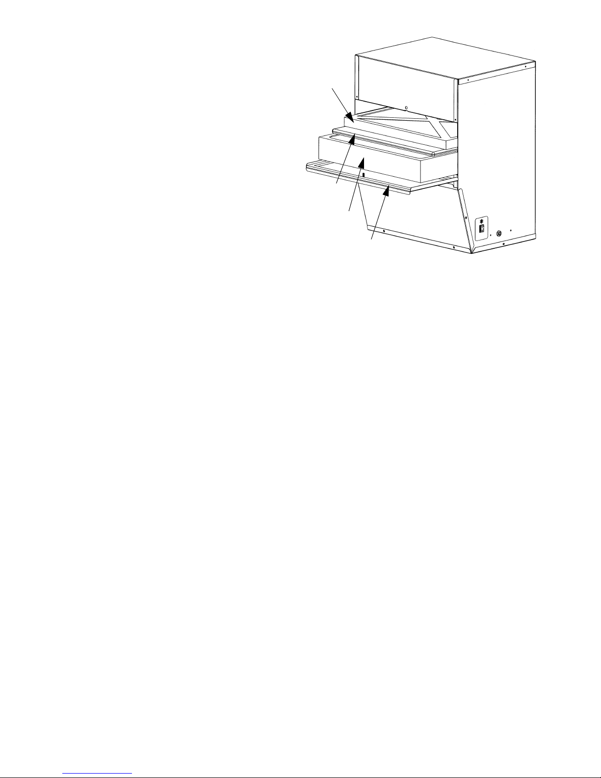
MAINTENANCE
For efficient operation, the filters must be changed on a
regular basis. If you notice a reduction in airflow from the sys-
tem, check the filters. See Fig. 6.
1. To access the filters, turn the air cleaner OFF at the
switch and remove the front door.
2. Carefully remove filters to avoid spilling collected
contaminants. Dispose of filters in a plastic bag and
discard with regular household trash.
Do not use the unit without all of the filters in place. The
HEPA filter life will be reduced.
Make sure to turn air cleaner OFF before performing any
maintenance or removing any components.
Fig. 5 — Collar Mount Installation