Tisira TG60 User manual

pg 1
tisira | www.tisira.com
USER MANUAL
600 & 900 // GAS HOBS
TG60 | TGW60 | TGWF60 | TGWF90
IMPORTANT // Please ensure that you read through this user manual prior to installation and use. This manual
contains important information to ensure optimal performance and keep you safe. Please retain your proof
of purchase, as this will be required in the event that you require warranty service. Remember to retain this
manual for future reference.
www.tisira.com

pg 2
www.tisira.com | tisira
CONGRATULATIONS ON THE SELECTION OF THIS TISIRA APPLIANCE. TISIRA
APPLIANCES HAVE BEEN SPECIFICALLY DESIGNED FOR AUSTRALIAN AND
NEW ZEALAND KITCHENS.
Please read through this user manual carefully as it contains information that
will ensure that your appliance is installed correctly, important operating & care
instructions and also some advice of what you need to do if this appliance is not
performing as intended.
HELLO

pg 3
tisira | www.tisira.com
CONTENTS
HELLO 2
CONTENTS 3
WARNING & SAFETY INFORMATION 4
PRODUCT OVERVIEW 5
INSTALLATION 6-11
OPERATING INSTRUCTIONS 12-13
MAINTAINING YOUR COOKTOP 14
PRODUCT SPECIFICATIONS 15
WARRANTY TERMS & CONDITIONS 16
PROOF OF PURCHASE 17
NOTES 18-19
CONTACT DETAILS 20

pg 4
www.tisira.com | tisira
WARNING
& SAFETY
INFORMATION
This appliance is not intended for use by persons (including children) with reduced physical,
sensory or mental capabilities, or lack of experience and knowledge, unless they have been given
supervision or instruction concerning use of the appliance by a person responsible for their safety.
Young children should be supervised to ensure that they do not play with the appliance.
There shall be adequate ventilation of the room when the rangehood is used at the same time as
appliances burning gas or other fuels.
You must read the details concerning the method and frequency of cleaning.
If the supply cord of this equipment is damaged, it must only be replaced by the manufacturer or
its service agent or a similarly qualified person in order to avoid a hazard.
This appliance has been designed for indoor domestic use only.
Do not use or store flammable materials near this appliance.
Do not spray aerosols in the vicinity of this appliance while it is in operation.
Do not modify this appliance
Where this appliance is installed in a marine craft or in caravans, it shall not be used as a
space heater.

pg 5
tisira | www.tisira.com
PRODUCT OVERVIEW
COMPONENT IDENTIFICATION
1. Auxiliary Gas Burners
2. Semi-rapid burner
3. Rapid burner
4. Triple ring burner
5. Igniter for Gas Burners (only on certain models)
6. Safety Device – Flame Failure (only on certain models) activates if the flame accidentally
goes out (spills, drafts, etc.), interrupting the delivery of gas to the burner.
7. Control Knobs for Gas Burners
1
7
11
22
2
6
5
2
22
3
3
4
4
7 7

pg 6
www.tisira.com | tisira
INSTALLATION
NOTICE // Must be installed by an authorized person in accordance with AS5601 (gas installations),
local authority and any other statutory regulations.
The following instructions are directed at the qualified installer so that the installation and
maintenance procedures may be followed in the most professional and expert manner
possible.
IMPORTANT // Ensure appliance is disconnected from the electrical supply before performing
any maintenance or regulation upkeep work.
Gas inlet is located at the rear right OR left hand side depending on the model 25mm from the
rear edge. Electrical terminal is located at the rear centre 50mm from the rear edge.
Fixing brackets are provided which allow the hob the hob to be installed in 20-40mm benchtops.
It is recommend to use all supplied brackets to ensure that the hob is secularly installed.
Bracket Position
20mm top
Bracket Position
30mm top
Bracket Position
40mm top
84
90
pg 7
tisira | www.tisira.com
POSITIONING FOR GAS HOB
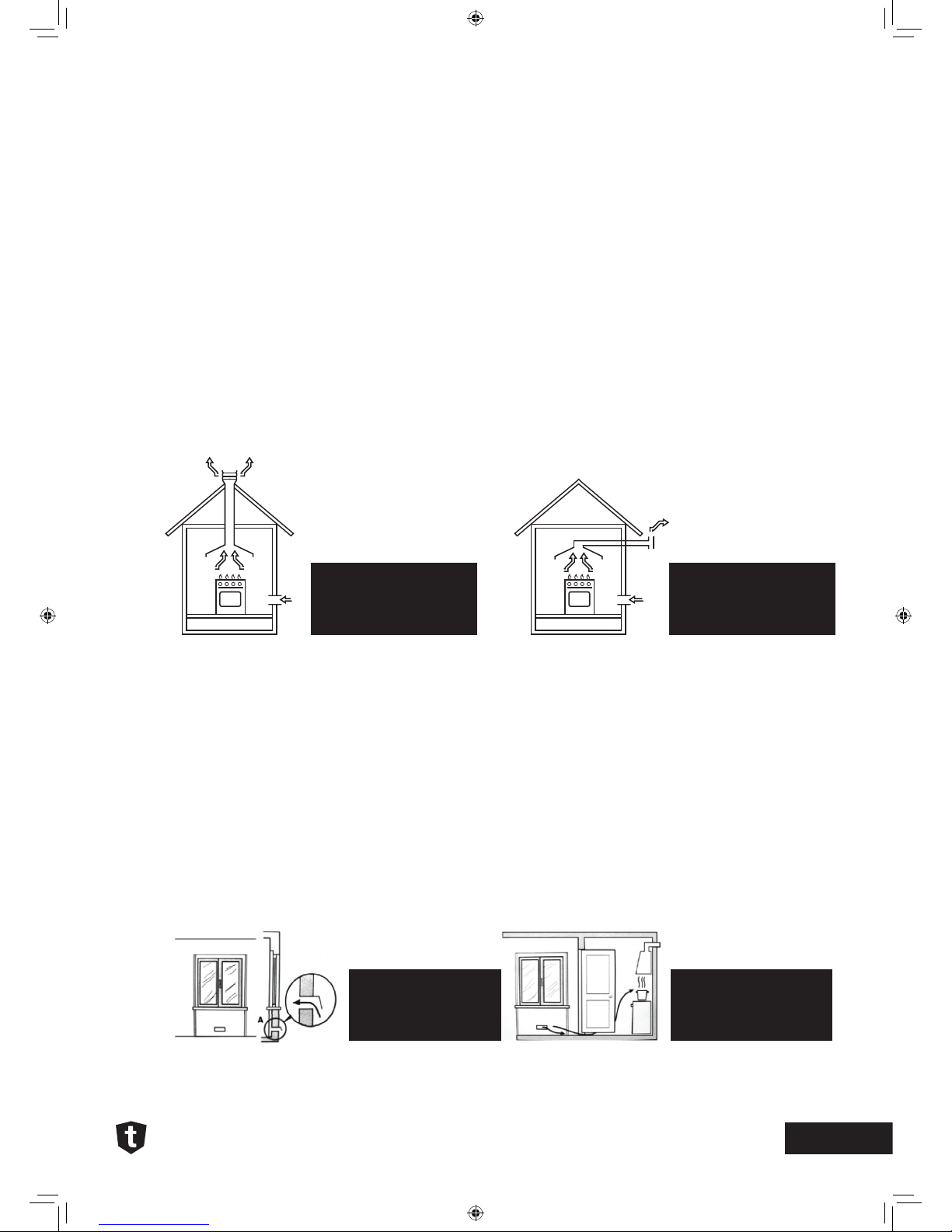
IMPORTANT // This unit may be installed and used only in permanently ventilated rooms in
accordance with AS5601 (gas installations), local authority and any other statutory regulations.
The following requirements must be observed:
A The room must be fitted with a ventilation system which vents smoke and gases from
combustion to the outside. This must be done by means of a hood or electric ventilator
that turns on automatically each time the hood is operated.
B The room must also allow for the influx of the air needed for proper combustion. The flow
of air for combustion purposes must, not be less than 2m3/h per kW of installed capacity.
The supply of said air can be affected by means of direct influx from the outside through a
duct with a inner cross section of at least 100cm2 which must not be able to be accidentally
blocked. Those appliances which are not fitted with a safety device to prevent the flame from
accidentally going out must have a ventilation opening twice the size otherwise required, i.e. a
minimum of 200 cm2 (Fig. A). Otherwise, the room can be vented indirectly through adjacent
rooms fitted with ventilation ducts to the outside as described above, as long as the adjacent
rooms are not shared areas, bedrooms or present the risk of fire (Fig. B).
INSTALLATION
In a chimney stack or
branched flue. (Exclusively
for cooking appliances)
Directly to the outside
Examples of Ventilation
Holes for comburant air
- Fig. A
Detail A Adjacent Room | Room to be vented
Enlarging the Ventilation
slots between the window
and floor - Fig. B
Bracket Position
40mm top

pg 8
www.tisira.com | tisira
INSTALLATION
C Intensive and prolonged use of the appliance may necessitate supplemental ventilation, e.g.
opening a window or increasing the power of the air intake system (if present).
D Liquefied petroleum gases are heavier than air and, as
a result, settle downwards. Rooms in which LPG tanks
are installed must be fitted with ventilation openings
to the outside in order to allow the gas to escape in the
event of a leak. Therefore, LPG tanks, whether empty or
partially full, must not be installed or stored in rooms
or spaces below ground level’ (cellars, etc.). It is also a
good idea to keep only the tank currently being used
in the room, making sure that it is not near sources of
heat (ovens, fireplaces, stoves, etc.) that could raise
the internal temperature of the tank above 50ºC.
E Overhead clearances—(Measurement A) Rangehoods and exhaust fans shall be installed
in accordance with the manufacturer’s relevant instructions. However, in no case shall
the clearance between the highest part of the hob of the gas cooking appliance and a
range hood be less than 600 mm or, for an overhead exhaust fan, 750 mm.
Side clearances—(Measurements B, & C) Where B, measured from the periphery of
the nearest burner to any vertical combustible surface, or vertical combustible surface
covered with toughened glass or sheet metal, is less than 200 mm, the surface shall
be protected to a height C of not less than 150 mm above the hob for the full dimension
(width or depth) of the cooking surface area. Where the gas cooking appliance is fitted
with a ‘splashback’, protection of the rear wall is not required.
F In the event the cooktop is not installed above a built-in oven, a wood panel must be
inserted as insulation. This panel must be placed at least 20 mm from the bottom of the
cooktop itself.
IMPORTANT // When installing the hob above a built-in oven, the oven should be placed on
two wooden strips; in the case of a joining cabinet surface, remember to leave a space of at
least 45 x 560 mm at the back.

pg 9
tisira | www.tisira.com
When installing on a built-in oven without forced ventilation, ensure that there are air inlets
and outlets for ventilating the interior of the cabinet adequately.
GAS CONNECTION FOR GAS HOB
The gas cooktop should be connected to the gas-supply by an authorised person only. During
installation of this product it is essential to fit an approved gas tap to isolate the supply from
the appliance for the convenience of any subsequent removal or servicing. Connection of
the appliance to the gas mains or liquid gas must be carried out according to the prescribed
regulation in force, and only after it is ascertained that it is adaptable to the type of gas to be
used. If not, follow the instructions indicated in the paragraph headed “Adaptation to different
gas types”. In the case of connection to liquid gas, by tank, use pressure regulators that
conform to the regulation in force.
IMPORTANT // For safety, for the correct regulation of gas use and long life of the appliance,
ensure that the gas pressure conforms to the indications given in the Product Specification
section of this manual under the heading “Nozzle and burner characteristics”.
CONNECTION TO NON-FLExIBLE TUBE
Copper or Steel // Connection to the gas source must be done in such a way as to not create
any stress points at any part of the appliance. The appliance is fitted with an adjustable, “L”
shaped connector and a gasket for the attachment to the gas supply. Should this connector
have to be turned, the gasket must be replaced (supplied with the appliance). The feeding
connector of the gas to the appliance is threaded 1/2” gas male cylinder.
CONNECTION TO FLExIBLE HOSE
The gas feed connector to the appliance is a threaded, male 1/2” connector for round gas
pipe. Only use pipes and sealing gaskets that that conform to the standards currently in force.
Flexible hose must be certified to AS1869 class B or D 10mm in diameter and no longer than
INSTALLATION

pg 10
www.tisira.com | tisira
INSTALLATION
1200mm long. The hose must not be kinked or be able to touch any hot surface. The supply
connection point must be accessible when installed.
CHECKING THE SEAL
Once the appliance has been installed, make sure all the connections are properly sealed,
using a soapy water solution. Never use a flame.
ELECTRICAL CONNECTION
The cooktops fitted with a tripolar electrical supply cord are designed to be be used with alternating
current according to the indications on the rating plate located under the cooktop. The earth wire
can be identified by its yellow-green colour. In the case of installation over a built-in electric oven,
the electrical connections for the cooktop and oven should be independent, not only for safety
purposes, but also to facilitate removal of one or both in the future.
ELECTRICAL CONNECTION FOR GAS COOKTOP
The supply cord has been fitted with a 10A 3 pin plug. The power supply cord must be positioned
so that it does not reach a temperature in excess of 50degC above room temperature at any point.
Before actual connection make sure that:
• The fuse and electrical system can withstand the load required by the appliance;
• That the electrical supply system is equipped with an efficient earth hook-up according to
the norms and regulations prescribed by law;
• That the plug and switch are easily accessible after installation.
Important // the wires in the mains lead are coloured in accordance with the following code:
Green & Yellow - Earth
Blue - Neutral
Brown - Live
As the colours of the wires in the mains lead may not correspond with the coloured markings
identifying the terminals in your plug, proceed as follows: Connect the Green & Yellow wire
to terminal marked “E” or coloured Green or Green & Yellow.
Connect the Brown wire to the terminal marked “L” or coloured Red.
Connect the Blue wire to the terminal marked “N” or coloured Black.
This manual suits for next models
5
Table of contents
Other Tisira Hob manuals

Tisira
Tisira TGWF30G User manual

Tisira
Tisira TCT61 User manual

Tisira
Tisira TIS60B User manual

Tisira
Tisira TCT90 User manual

Tisira
Tisira tIs90b User manual

Tisira
Tisira TIT63E User manual

Tisira
Tisira TIT60 User manual

Tisira
Tisira TGF64E User manual

Tisira
Tisira tIs90b User manual

Tisira
Tisira TCT63E User manual