TeraBee TeraRanger Evo Series User manual

User Manual for
TeraRanger Evo Mini
Technical support: [email protected]
Sales and commercial inquiries: [email protected]

Table of contents
1. Introduction 4
1.1. About Terabee 4
1.2. Symbols explanation 4
1.3. Technical Specifications 5
1.3.1. Performance Matrix 6
1.3.2 Communication interfaces 6
1.4. Pixel modes introduction 7
2. Mechanical integration 8
2.1. Modular design (clip-on, clip-off) 8
2.2. Mechanical design and mounting 8
2.3. Mounting solutions 10
3. USB backboard use 11
3.1. LED Indication 11
3.1.1. Normal operation 11
3.1.2. Error messages and troubleshooting 11
3.2. Graphical User Interface (version 1.0.31) 12
3.2.1. Prerequisites 13
3.2.2. Basic Operation with the GUI, supporting 1px mode 13
3.2.3 Firmware Upgrade 14
3.3. Connecting the TeraRanger Evo to a Host Computer 15
3.3.1 Windows OS 15
3.3.2 Mac Os 16
4. I2C/UART backboard use 18
4.1. I2C/UART pinout 18
4.2. LED Indicators 19
4.2.1. Normal operation 19
4.2.2.Troubleshooting 19
4.3. Electrical characteristics 20
5. USB/UART Normal operation 20
5.1. USB/UART list of commands 20
5.2. Printout modes: text and binary 21
5.2.1. TEXT mode 21
5.2.2. BINARY mode (default) 22
5.3. Pixel modes: 1px, 2px and 4px 23
5.3.1 1px mode 23
5.3.2 2px mode 23
Copyright © Terabee 2019
Terabee, 90 Rue Henri Fabre
01630, St Genis-Pouilly, France (next to CERN)
2/29

5.3.3 4px mode 23
5.4 Range modes: short-range and long-range 24
5.4.1. Long range mode (default) 24
5.4.2. Short range mode 24
5.5 Error cases 24
6. I2C normal operations 25
6.1 I2C Protocol information 25
6.1.1. Write protocol 25
6.1.2. Read protocol 27
6.2. Error cases 27
7. Build multi-sensor applications 28
8. Optical characteristics 29
8.1. Projected reception area 29
Copyright © Terabee 2019
Terabee, 90 Rue Henri Fabre
01630, St Genis-Pouilly, France (next to CERN)
3/29

1. Introduction
1.1. About Terabee
The smallest and lightest addition to the TeraRanger Evo sensor family provides versatile
performance and value for money! Optimized for indoor distance sensing, Evo Mini offers
ranging capabilities from just 3 cm up to 3.3 m using a 27 degree Field of View. Easily
switch from single-pixel to multi-pixel modes, as well as close-range and long-range modes,
to adapt to your sensing needs.
Figure 1. TeraRanger Evo Mini sensors, top view
Evo Mini has zero open electronics and provides an ABS protected enclosure, resulting into
a dust-proof and robust operation. Benefit from Arduino & Raspberry Pi sample codes and
free ROS packages to get your projects up and running in no time!
1.2. Symbols explanation
The following symbols are used within the document:
This symbol indicates specific recommendations in order to run the sensor in the
intended way.
Copyright © Terabee 2019
Terabee, 90 Rue Henri Fabre
01630, St Genis-Pouilly, France (next to CERN)
4/29

1.3. Technical Specifications
Table 1 - Technical specifications of TeraRanger Evo Mini
Product codes
TR-EVO-MINI-USB / TR-EVO-MINI-I2C
Performance
Detection Principle
Infrared Time-of-Flight
Light Source Wavelength
940 nm
Use Environment
Indoors
Repeatability
< 5 mm
Output Distance Resolution
1 mm
Field of View
27°
Projected Reception Area
48 cm x 48 cm @ 1 m
Operation
Pixel (px) modes: 1px, 2px, 4px (2x2)
Ranging modes: short-range, long-range
Range
Please see “Performance Matrix” table for more details
Accuracy
Update Rate
Electronics
Supply Voltage VDC
5V DC +/-5%
Current Consumption (average)
50mA
Initialization Time
< 1 s
Communication
Serial Interfaces
USB 2.0 Micro-B
UART, +3.3V level, 115200,8,1, None
I2C, +3.3V level, 400 kHz
Visual Notification
2 x LEDs (built-in backboard)
Mechanical data
Dimensions
42 x 30 x 13 mm (incl. backboard)
Weight
9 g (incl. backboard)
Operating Temperature
-20°C to 75°C
Housing Material
ABS
Copyright © Terabee 2019
Terabee, 90 Rue Henri Fabre
01630, St Genis-Pouilly, France (next to CERN)
5/29

Mounting Style
2 holes for M2 screws
Type of Connection
USB Backboard: USB 2.0 Micro-B
I2C/UART Backboard: DF13-7p connector
Hub Evo Backboard for use with TeraRanger Hub Evo
Conformity
CE, RoHS
1.3.1. Performance Matrix
Table 2 - Performance matrix for the different range and pixel modes
Range mode
Short-Range mode
Long-Range mode
Pixel mode
1px mode
2px mode
4px mode
1px mode
2px mode
4px mode
Range
0.03m to
1.35m
0.03m to
1.35m
0.03m up to
1.35m
0.03m to 3.3m
0.03m to 2.3m
0.03m up to
1.65m
Accuracy
Up to
+/-1.5cm
Up to +/-1.5cm
Up to +/- 2cm
Up to +/- 2cm
Up to +/-1.5cm
Up to +/- 3cm
Update Rate
Fixed 40Hz
Fixed 13Hz
Fixed 6Hz
Fixed 20Hz
Fixed 8Hz
Fixed 4Hz
Specifications are derived from tests in controlled conditions (target with 80% diffuse reflectivity, indoor fluorescent lighting,
ambient temperature around 25°C). Note that bright sunlight, target surface reflectivity and other variables can affect sensor
performance
1.3.2 Communication interfaces
Table 3 - Communication interfaces for the different range and pixel modes
Interfac
e
Short-Range mode
Long-Range mode
1px mode
2px mode
4px mode
1px mode
2px mode
4px mode
USB
Yes
Yes
Yes
Yes
Yes
Yes
UART*
Yes
Yes
Yes
Yes
Yes
Yes
I2C*
Yes
Yes
Hub Evo
Yes
*Please note that UART and I2C data communication is supported by the same interface backboard
Copyright © Terabee 2019
Terabee, 90 Rue Henri Fabre
01630, St Genis-Pouilly, France (next to CERN)
6/29

1.4. Pixel modes introduction
The TeraRanger Evo provides 6 operating modes: 3 pixel modes and 2 range modes. For
more details on how to switch between the operating modes, please refer to section 5.
Benefit from 3 distinct pixel modes with 1 pixel resolution, 2 pixel resolution and 4 pixels
(2x2) resolution. Please see table 4 for a visual example for each pixel mode.
Table 4 - TeraRanger Evo Mini operating modes introduction
1px mode
2px mode
4px mode (2x2)
Sensor outputs 1 distance.
Sensor outputs 2 distances.
Sensor outputs 4 distances on
a matrix of 2x2.
Copyright © Terabee 2019
Terabee, 90 Rue Henri Fabre
01630, St Genis-Pouilly, France (next to CERN)
7/29
2. Mechanical integration
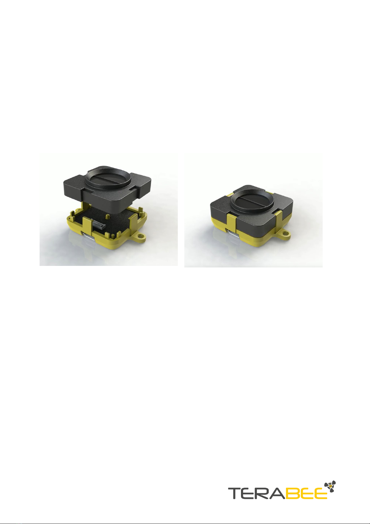
2.1. Modular design (clip-on, clip-off)
The mechanical design of the main sensor module (black) allows easy assembly to its
backboard (yellow) using a simple ‘clip-on’ technique. When clipping the two together,
please ensure there is no visible gap between the black and yellow parts.
Figure 2 - modular design of the TeraRanger Evo Mini sensor
2.2. Mechanical design and mounting
TeraRanger Evo Mini distance sensor offers an ABS housing (both: sensor and backboard)
with an option to mount the sensor using 2 holes compatible with M2 screws. Figure 3
illustrates external dimensions of TeraRanger Evo Mini sensor.
Copyright © Terabee 2019
Terabee, 90 Rue Henri Fabre
01630, St Genis-Pouilly, France (next to CERN)
8/29

Figure 3 - TeraRanger Evo Mini external dimensions, USB backboard
Please note that the overall sensor dimensions remain unchanged when using the
I2C/UART backboard. The only affected dimension is the opening of the connector.
Both USB and I2C/UART Backboards include two slots for mounting the sensor using
standard M2 screws. The following methods can be used to mount the TeraRanger Evo
Mini sensor:
1. Front-panel mount using the M2 screws
2. Back-panel mount using the 2mm ledge on the front side of the sensor
Figure 4 illustrates the two different mount methods. The prior solution allows for easy
surface attachment and rapid evaluation of the sensor. The latter provides a more discreet
installation and supports design-in projects by installing the sensor behind a surface (e.g
panel), ideally with 2mm thickness.
Copyright © Terabee 2019
Terabee, 90 Rue Henri Fabre
01630, St Genis-Pouilly, France (next to CERN)
9/29

Figure 4. Front-panel mounting (left image); back-panel mounting (right images)
2.3. Mounting solutions
When choosing a place for mounting the TeraRanger Evo Mini, please consider the
following recommendations:
●Mounting close to sources of heat or strong electromagnetic fields can decrease the
sensing performance
●Do not mount anything directly in front of the sensor or in a cone of approximately
+/-35° around the central optical axis of the sensor
●Within the first meter from the sensor, avoid objects with high surface reflectivity in
a cone of approximately +/-45° around the central optical axis of the sensor
●It is better to avoid having other sources of Continuous Wave or modulated IR light
close to the sensor
●Please consider that dust, dirt and condensation can affect the sensor performance
●It is not advised to add an additional cover in front of the sensor
During assembly and integration, please observe all common ESD precautions. All
optical surfaces (sensor front) should be kept clean and free from contact with
chemicals.
Copyright © Terabee 2019
Terabee, 90 Rue Henri Fabre
01630, St Genis-Pouilly, France (next to CERN)
10/29
This manual suits for next models
3
Table of contents
Other TeraBee Accessories manuals

TeraBee
TeraBee TeraRanger Evo User manual

TeraBee
TeraBee Follow-Me User manual

TeraBee
TeraBee TeraRanger One User manual

TeraBee
TeraBee TeraRanger Evo User manual

TeraBee
TeraBee TeraRanger Evo User manual

TeraBee
TeraBee ND-TOF-1 User manual

TeraBee
TeraBee TeraRanger Neo ES User manual

TeraBee
TeraBee TeraRanger Evo Swipe Plus User manual

TeraBee
TeraBee TeraRanger Multiflex User manual

TeraBee
TeraBee IND-TOF-1 User manual


