Sony SDT-D9000 Manual

SDT-D11000/D9000
DDS Drive Unit
4-653-886-11(1)
Operator’s Guide –––––––––page 2
Mode d’emploi –––––––––––page 21
Benutzerhandbuch –––––––Seite 39
Guía del operador ––––––––página 58
© 2001 Sony Corporation

2
Safety Regulations
Owner’s Record
The model and serial numbers are located on the bottom. Record the serial
number in the space provided below.
Refer to them whenever you call upon your Sony dealer regarding this
product.
Model No. Serial No.
Information
WARNING
To prevent fire or shock hazard, do not expose the
unit to rain or moisture.
To avoid electrical shock, do not open the cabinet.
Refer servicing to qualified personnel only.
For the customers in the U.S.A.
You are cautioned that any changes or modifications not expressly approved
in this manual could void your authority to operate this equipment.
WARNING
Note: This equipment has been tested and found to comply with the limits
for a Class B digital device, pursuant to Part 15 of the FCC Rules. These
limits are designed to provide reasonable protection against harmful
interference in a residential installation. This equipment generates, uses and
can radiate radio frequency energy and, if not installed and used in
accordance with the instructions, may cause harmful interference to radio
communications. However, there is no guarantee that interference will not
occur in a particular installation. If this equipment does cause harmful
interference to radio or television reception, which can be determined by
turning the equipment off and on, the user is encouraged to try to correct the
interference by one or more of the following measures:
• Reorient or relocate the receiving antenna.
• Increase the separation between the equipment and receiver.
• Connect the equipment into an outlet on a circuit different from that to
which the receiver is connected.
• Consult the dealer or an experienced radio/TV technician for help.

3
CAUTION
The mains plug on this equipment must be used to disconnect mains power.
Please ensure that the socket outlet is installed near the equipment and shall
be easily accessible.
NOTICE
Use the power cord set approved by the appropriate testing organization for
the specific countries where this unit is to be used.
If you have any questions about this product, you may call:
Sony Technical Support, 1-800-588-3847 or write to :
Sony Technical Support, 3300 Zanker Road, San Jose, CA 95134, 1940.
U.S.A.
DECLARATION OF CONFORMITY
Trade Name: Sony
Model No: SDT-D11000/D9000
Responsible Party: Sony Electronics, Inc.
Address: 680 Kinderkamack Road, Oradell NJ 07649 U.S.A.
Telephone: 201-930-6972
This device complies with part 15 of the FCC Rules.
Operation is subject to the following two conditions:
(1) This device may not cause harmful interference.
(2) This device must accept any interference received, including
interference that may cause undesired operation.
This device requires shielded interface cables to comply with FCC emission
limits.
English

4Table of Contents
Table of Contents
How to Use this Guide ...................................................................... 5
Part 1
Introduction
About DDS Drives ............................................................................. 6
Features....................................................................................................6
Useable Cartridges...................................................................................7
System Components ................................................................................7
Part Names and Functions............................................................... 8
Front Panel...............................................................................................8
Rear Panel..............................................................................................10
Part 2
Preparation
Supplied Items................................................................................. 11
Interconnections ............................................................................. 11
SCSI ID Setting ................................................................................ 12
Part 3
Operation
How to use the DDS Drive .............................................................. 13
Cartridge Removal.................................................................................14
Part 4
Care and
Maintenance
Taking Care of the Drive................................................................. 15
Safety Considerations ............................................................................15
Avoiding Damage..................................................................................15
Taking Care of Cartridges .............................................................. 17
Use Precautions .....................................................................................17
Storage Precautions ...............................................................................17
Head Cleaning ................................................................................. 18
How to Clean .........................................................................................18
Appendix Specifications (SDT-D11000) ......................................................... 19
Specifications (SDT-D9000) ........................................................... 20

5
How to Use this Guide
This Guide describes the DDS Drive Unit SDT-D11000/D9000 , and how to
take care of it. Please read it carefully before using the unit, and keep it handy
for future reference.
The Guide consists of four parts, plus the specifications. Refer to the parts
that relate to your use of the drive.
Part 1 describes the features of the drive, its system components, and the
name and function of each part.
Part 2 describes the necessary connections between the drive and the host
computer. If other SCSI devices are being used, you may need to change the
SCSI ID setting. Read this part if you are installing the drive.
Part 3 describes how to use the drive, including how to turn it on, and how
to insert and remove cartridges. Read this part if you are going to operate the
drive.
Part 4 describes how to take care of the drive and cartridges, and how to
clean the drive heads. Read this part before using the drive.
The Specifications Appendix provides the major specifications of the
SDT-D11000/D9000.

6Part 1. Introduction
Part 1. Introduction
About DDS Drives
The SDT-D11000 is an external DDS drive unit that uses data cartridges
conforming to the DDS-4 format. The SDT-D9000 is an external DDS drive
unit that uses data cartridges conforming to the DDS-3 format. The SDT-
D11000 supports DDS-1, DDS-2, DDS-3 and DDS-4 formats. The SDT-
D9000 supports DDS-1, DDS-2 and DDS-3 formats.
Features
The DDS Drive Unit SDT-D11000 has the following features:
•The Digital Data Storage format provides a huge data storage capacity on
DDS-1/DDS-2/DDS-3/DDS-4 data cartridges.
•Read After Write Function and third-level error correction code guarantee
high data reliability.
•Data compression provides 40 gigabytes of storage on 150 m tape-length
cartridge.*1
The native capacity is 20 gigabytes of storage on 150 m tape-length
cartridge.
•Stored data are automatically checked for compression.
•Embedded wide ultra SCSI interface.
(LVD/SE automatically switchable)
•Supports SCSI-2 sequential-access devices command set.
•Read/Write operation is available with DDS-1, DDS-2, DDS-3 and DDS-4
formats.
The DDS Drive Unit SDT-D9000 has the following features:
•The Digital Data Storage format provides a huge data storage capacity on
DDS-1/DDS-2/DDS-3 data cartridges.
•Read After Write Function and third-level error correction code guarantee
high data reliability.
•Data compression provides 24 gigabytes of storage on 125 m tape-length
cartridge.*1
The native capacity is 12 gigabytes of storage on 125 m tape-length
cartridge.
•Stored data are automatically checked for compression.
•The SCSI-2 (ANSI SCSI-2 X3T9.2/86-109 REV. 10C) interface is fully
supported for host computer access.
•Read/Write operation is available with DDS-1, DDS-2 and DDS-3 formats.
*1 This is assuming 2 : 1 compression ratio.
The degree of data compression attained while recording data varies according to system
environment and data type.

Part 1. Introduction 7
Useable Cartridges
Data cartridges used with the SDT-D11000 must be marked with the DDS-1,
DDS-2, DDS-3 or DDS-4 logo. The SDT-D9000 can only be used with data
cartridges marked with DDS-1, DDS-2 or DDS-3 logo.
DDS-4 Logo DDS-3 Logo DDS-2 Logo DDS-1 logo
Caution
Be sure to use only the cartridges designed specifically for DDS (do not use
DAT cartridges for music).
System Components
The SDT-D11000 connects to the host computer via a wide ultra SCSI
interface.
The SDT-D9000 connects to the host computer via a SCSI-2 interface.
Figure 1-1. Example of System Components
SDT-D11000/D9000
Host Computer
SDT-D11000: Up to 15 peripherals
Peripheral Devices

8Part 1. Introduction
Part Names and Functions
Front Panel
BUSY TAPE STATUS
POWER
12
76543
Figure 1-2. Front panel
1DDS Data Cartridge Receptacle
See page 13 for information on inserting and removing a DDS data
cartridge.
2POWER Indicator
Lights while the drive is on.
3BUSY Indicator
Lights when data is being transferred through the SCSI interface. This
indicator also lights under the following conditions:
4TAPE Indicator
When a DDS cartridge is installed, this indicator lights. This also lights
under the following conditions:
Drive is reading or writing normally: repeated blinking (same on-off
interval).
Inserting and removing a cartridge: repeated blinking (same on-off
interval).
Cartridge deteriorated: alternating long-short blinking.

Part 1. Introduction 9
5STATUS Indicator
Lights when an inserted cartridge is write-protected. This indicator also
lights under the following conditions:
6EJECT Button
Push to remove a data cartridge from the drive.
7POWER Switch
Press to turn the drive on or off.
Drive needs cleaning: repeating long-on, short-off
blinking.
End of Tape during cleaning: repeating blinking (same on-off
interval).
Drive Malfunctioning: repeating short-on (once or twice),
long-off blinking.
10 Part 1. Introduction
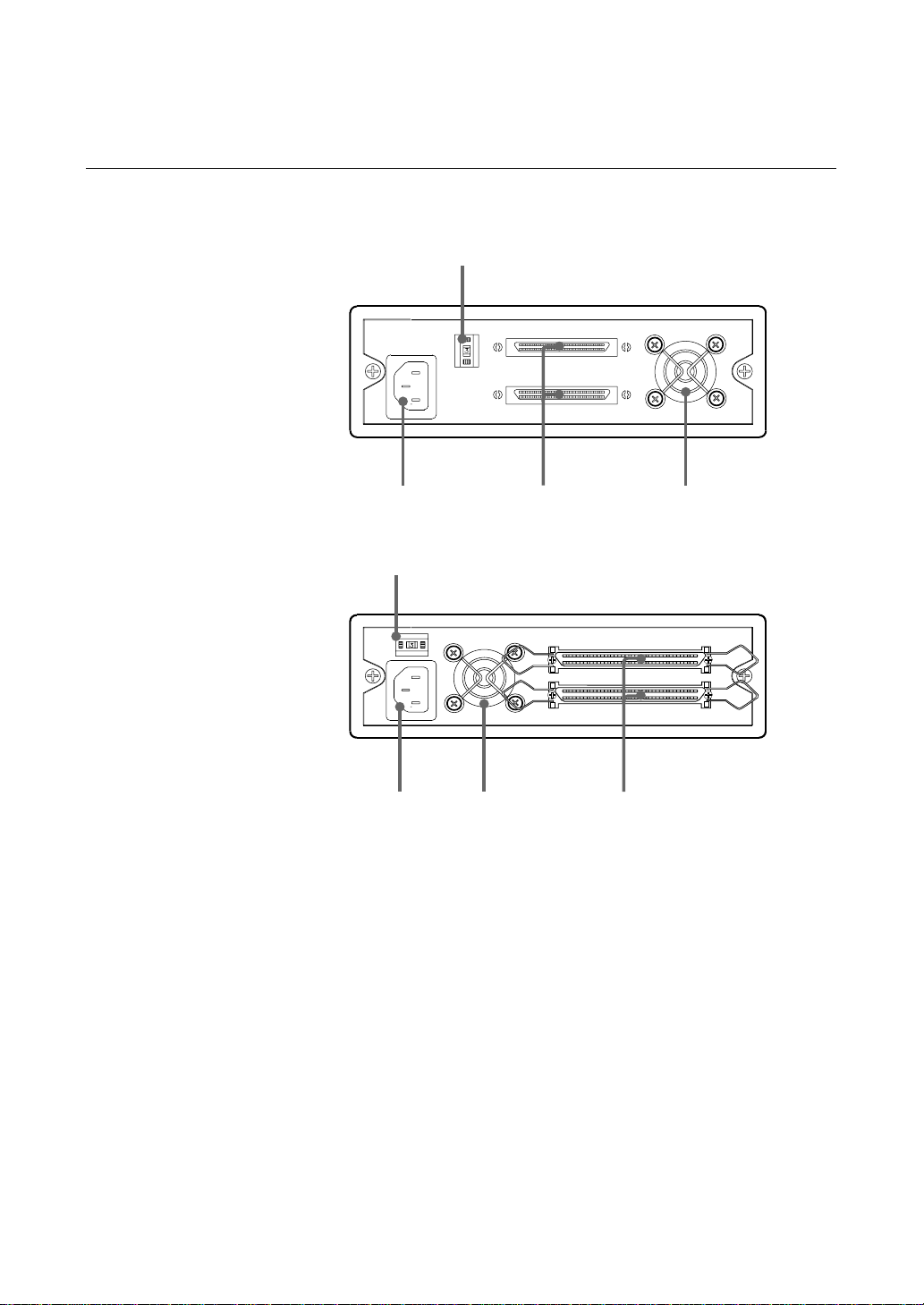
Rear Panel
SDT-D11000
1
234
SDT-D9000
1
24 3
Figure 1-3. Rear Panel
1Rotary Selector Switch
SCSI ID selector.
2AC IN Connector
Connect the supplied power cable here.
3SCSI Connector
Connects to the SCSI bus connector of the host computer or another
SCSI peripheral.
4Cooling Fan
This manual suits for next models
1
Table of contents
Languages:
Other Sony Storage manuals

Sony
Sony MSH-128S2 User manual

Sony
Sony MicroVault USM2GL User manual

Sony
Sony SF SERIES User manual

Sony
Sony ERA-MS008 User manual

Sony
Sony VPCEB Series Guide

Sony
Sony SDX-700C User manual

Sony
Sony HD-B1 User manual

Sony
Sony VAIO PCGA-HD740 User manual

Sony
Sony SDZ-100 User manual

Sony
Sony USD2G User manual

Sony
Sony MSX-256 User manual

Sony
Sony VPCL211FX Guide

Sony
Sony HD-B1 User manual

Sony
Sony ODS-L30M User manual

Sony
Sony ODS-L60E User manual

Sony
Sony PHU-60K Series User manual

Sony
Sony PCGA-MM532SD User manual

Sony
Sony HDPS-M10 - Data Storage Wallet User manual

Sony
Sony IPELA NSRE-S200 User manual

Sony
Sony CSM-200C User manual


