Siemens SL10 User manual

Private Communication Systems
Mobile Phones
Service Manual SL10 V1.1 PN MP ST
R. Fleuren
Sm_sl10_lvl2_v11.doc Page 1 of 22 05/98
Service Manual
SL 10
V 1.1

Private Communication Systems
Mobile Phones
Service Manual SL10 V1.1 PN MP ST
R. Fleuren
Sm_sl10_lvl2_v11.doc Page 2 of 22 05/98
1 Table of Contents
1 TABLE OF CONTENTS....................................................................................................................................2
2 TECHNICAL DATA ..........................................................................................................................................3
3 GENE AL INFO MATION ............................................................................................................................4
4 MECHANICAL CONCEPT..............................................................................................................................4
4.1 MECHANICAL DRAWING OF THE SL10.................................................................................................................5
4.2 DISASSEMBLING THE SL10 .................................................................................................................................6
4.2.1 Necessary ools .......................................................................................................................................6
4.2.2 Disassembling he Mobile.......................................................................................................................6
4.2.3 Disassembling he Slide ..........................................................................................................................8
4.2.4 Disassembling he Top Par of he Base .................................................................................................9
4.2.5 Disassembling he Bo om Par of he Base..........................................................................................10
4.3 ASSEMBLING THE SL10 ....................................................................................................................................10
4.3.1 Assembling he Bo om Par of he Base ..............................................................................................10
4.3.2 Assembling he Top Par of he Base....................................................................................................11
4.3.3 Assembling he Slide ............................................................................................................................11
4.3.4 Assembling he Mobile .........................................................................................................................12
4.4 HANDSET DATECODES ......................................................................................................................................13
5 HA DWA E CONCEPT................................................................................................................................14
5.1 BLOCK DIAGRAM..............................................................................................................................................14
5.2 HARDWARE DESCRIPTION.................................................................................................................................15
5.3 POWER SUPPLY CONCEPT .................................................................................................................................16
5.4 LIMITS OF VOLTAGE AND CURRENT..................................................................................................................17
6 BATTE Y .........................................................................................................................................................18
6.1 SPECIFICATION..................................................................................................................................................18
6.2 SHORT CIRCUIT PROTECTION............................................................................................................................18
6.3 DEEP DISCHARGE..............................................................................................................................................18
6.4 BATTERY DATECODES ......................................................................................................................................19
7 SOFTWA E P OG AMMING ....................................................................................................................20
7.1 DESCRIPTION OF SOFTWARE BOOTING...............................................................................................................20
7.2 LANGUAGE GROUPS..........................................................................................................................................21
8 UNBLOCKING.................................................................................................................................................21
8.1 SIEMENS HOTLINE.............................................................................................................................................21
8.2 INTERNET SOLUTION .........................................................................................................................................22

Private Communication Systems
Mobile Phones
Service Manual SL10 V1.1 PN MP ST
R. Fleuren
Sm_sl10_lvl2_v11.doc Page 3 of 22 05/98
2 Technical Data
Length: 129 mm
Width: 50 mm
Thickness: 26 mm
Volume: 121 cm³
Weight: 138 grams
Performance: GSM class 4 (2 Wa )
Frequency ange: Tx 890-915 MHz
Rx 935-960 MHz
Power supply: Li hium Ion ba ery (3,6V/550mAh)
Standby time: Up o 35 hours
Talk time: Up o 3 hours.
Charging time: approx. 1 hour
Display: LCD high-resolu ion colour graphic display
SIM Card Type: Plug-In, 3V or 5V
Antenna: Non-re rac able, Lambda/2 helix ype

Private Communication Systems
Mobile Phones
Service Manual SL10 V1.1 PN MP ST
R. Fleuren
Sm_sl10_lvl2_v11.doc Page of 22 05/98
3 General Information
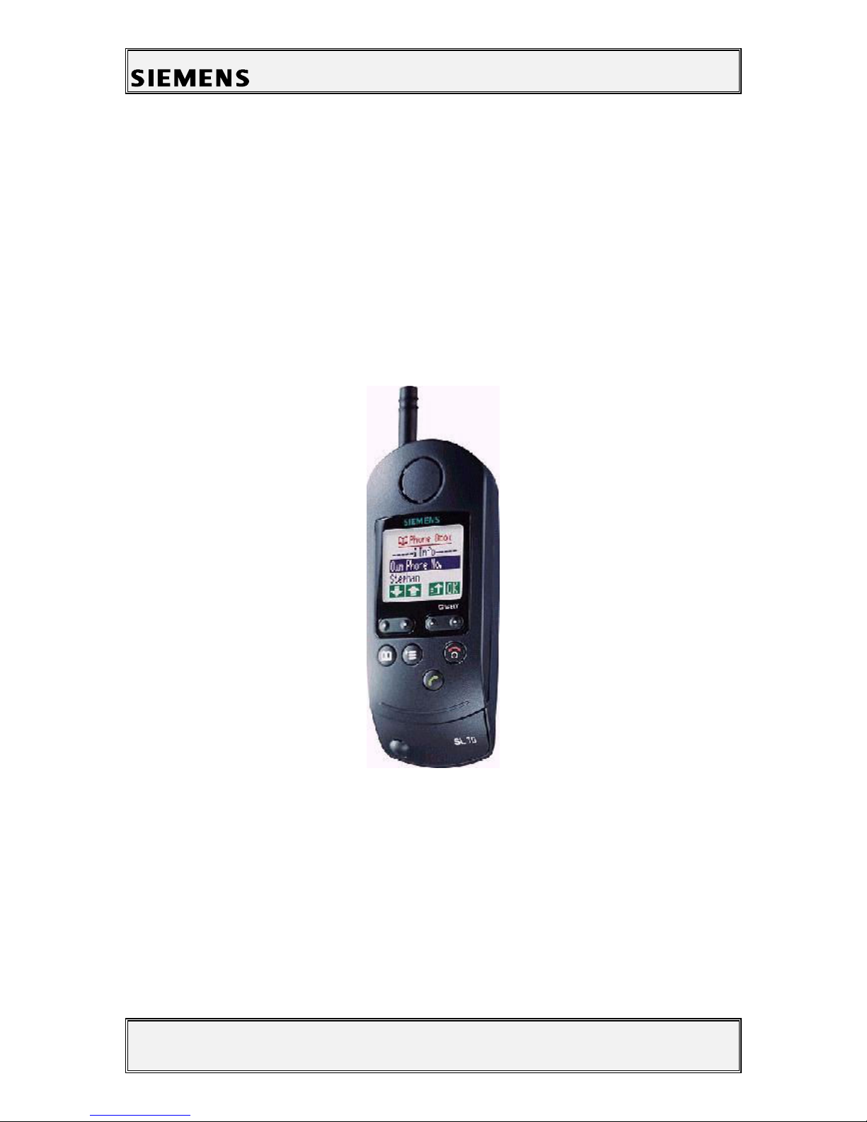
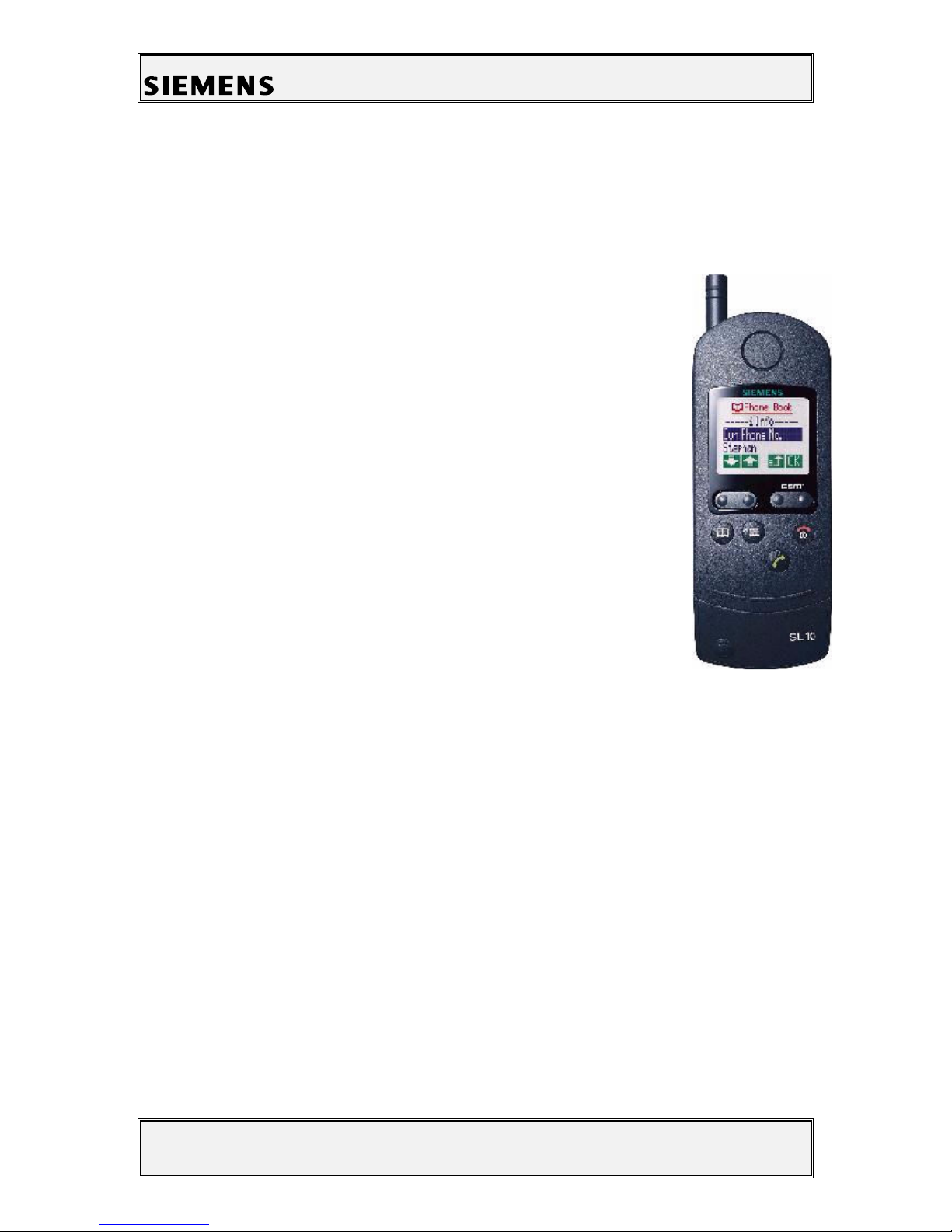
The SL10 is he firs Siemens mobile GSM elephone using
he new MCM chipse echnology. I fur her consis s of a
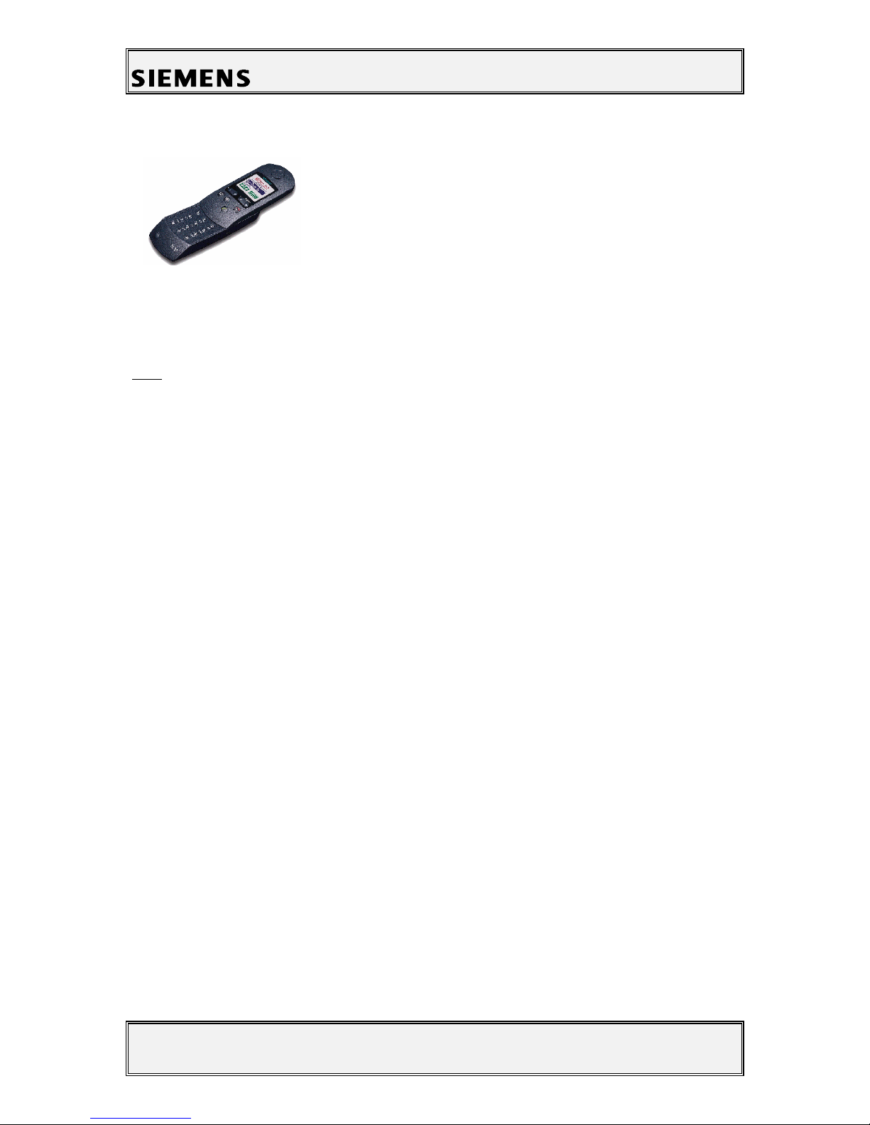
slide mechanism, he so called ProSLIDETM system, which
e.g. suppor s ON-Hook and OFF-hook func ion. As in
S10ac ive, he SL10 also fea ures a real ime clock.
Addi ionally i is equipped wi h an infrared in erface e.g. for
da a ransmission.
Mechanical Concept
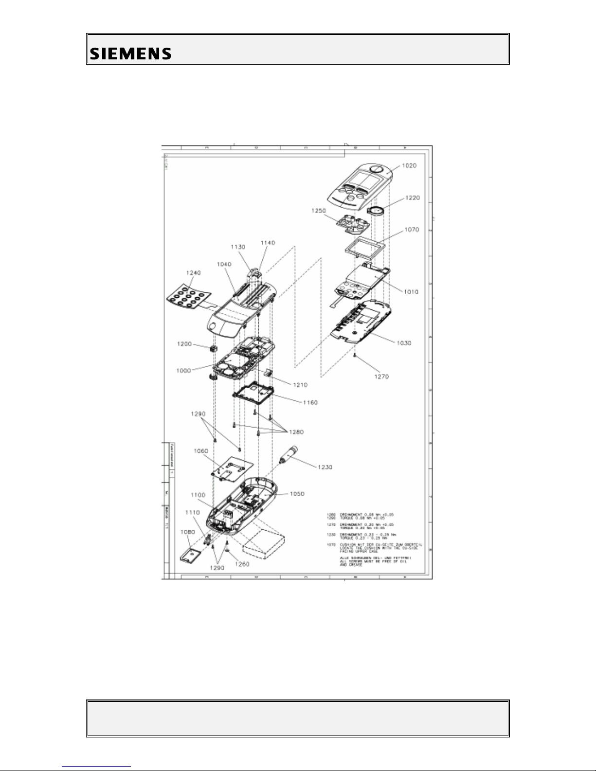
Note: All part numbers refer to mechanical drawing in section 4 1! These numbers are not
valid for ordering spare parts For appropriate ordering numbers please refer to the official
spare part list If you have questions regarding spare parts, please contact your service
manager
The SL10 consis s of wo major par s: The slide uni and he base uni . User in erface
compared o o her Siemens mobiles is no realised by jus one MMI board con aining all
necessary componen s, bu is separa ed in o a MMI board (1010) inside he slide uni which
carries display and a par of he keypad (1250), and a second keypad (1240) inside of he base
uni . Microphone (1200) also is loca ed in he base uni .
The connec ion be ween MMI board and RF&Con rol board is no es ablished by a normal
connec or wi h plug-in con ac s or an in erconnec or (e.g. like in S6), bu by a flexible cable.
The same kind of cable is used o connec he keypad (1240) and microphone (1200) inside of
he base uni o he RF&Con rol board (1000). The one end of hese cables is soldered o he
appropria e board, he o her end is plugged in o a ZIF-connec or (ZIF= Zero Inser ion Force).
Attention:
The flexible cables are very sensi ive o any kind of mechanical mis rea men . Please be
careful no o damage hem during he repair process of he elephone! Various kinds of
failures can come up even if hese cables are only bended.
The shielding concep is similar o he one of S6. The upper case (1040) of he base uni is
coa ed wi h a conduc ive ma erial and conduc ive rubber. This es ablishes he shielding of he
one side of RF&Con rol module (1010). On he opposi e side of his board here is a shielding
screen (1160) above he relevan area, which is fixed by four screws (1280). The an enna
(1230) is direc ly screwed in o he lower case (1050) of he base uni .
The keypad (1240), he loudspeaker (1220), dus pro ec ion frame (1070) and MMI board
(1010) are moun ed in o he upper case (1020) of he slide uni . Please make sure while
assembling he slide uni ha he me al con ac s of he dus pro ec ion frame (1070) are
properly ben up when moun ing.
When urning in he screws (1270, 1280, 1290) make sure ha he righ orque is used
(1280, 1290: (0,08+0,02)Nm; 1270: (0.2+0,05)Nm).

Private Communication Systems
Mobile Phones
Service Manual SL10 V1.1 PN MP ST
R. Fleuren
Sm_sl10_lvl2_v11.doc Page 5 of 22 05/98
4.1 Mechanical drawing of the SL10

Private Communication Systems
Mobile Phones
Service Manual SL10 V1.1 PN MP ST
R. Fleuren
Sm_sl10_lvl2_v11.doc Page 6 of 22 05/98
4.2 Disassembling the SL10
Caution!
Inside he elephone here are hree flexible cables, which are very sensi ive o any kind of
mechanical damage. Please be careful during all he disassembling process no o damage
hem e.g. by bending or snapping.
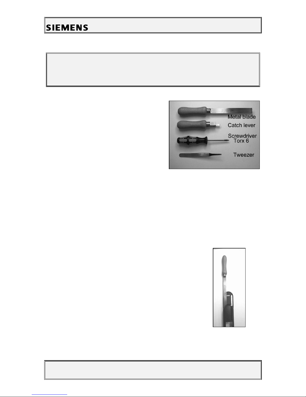
4.2.1 Necessary tools
For disassembling he SL10 he following ools are
manda ory:
- Me al blade
- Ca ch lever
- Screwdriver Torx 6
- Tweezer
4.2.2 Disassembling the Mobile
1. Remove ba ery and SIM-Card
2. Unscrew an enna.
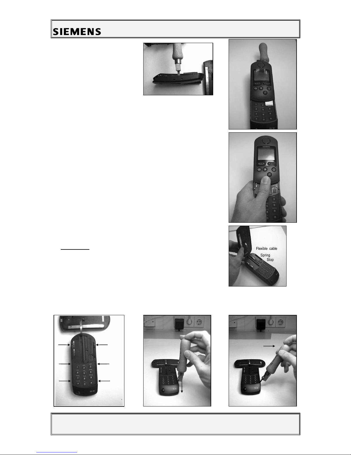
1. Remove he wo coun ersunk-head screws a he lower end of he elephone (below ven
plug) and inside he ba ery depar men .
2. Move slide all he way o he open posi ion.
3. Undo he slide s op by inser ing he me al s rip on he lef side
be ween he slide and he base.

Private Communication Systems
Mobile Phones
Service Manual SL10 V1.1 PN MP ST
R. Fleuren
Sm_sl10_lvl2_v11.doc Page 7 of 22 05/98
1. Turn he mobile over and
push he me al s rip hrough
un il i is visible above he
keypad.
1. Then use your humb o press he slide up o separa e i from
he base. The second s op which is moun ed a he bo om of
he slide has o be released a he same ime. To do so, push
he bo om of slide upwards and con inue pushing he slide
wi h he humb.
The me al blade can be removed when he s op on he op of
base is visible comple ely.
1. Remove spring and s op from op of base.
Attention:
Flexible cable is very sensi ive o any kind of mechanical
damage (e.g. bending, snapping).
1. Use he ca ch lever o unlock he six ca ches (see figures
below) in order o separa e he op par of he base from he bo om par of he base.
1 2
3 4
5 6

Private Communication Systems
Mobile Phones
Service Manual SL10 V1.1 PN MP ST
R. Fleuren
Sm_sl10_lvl2_v11.doc Page 8 of 22 05/98
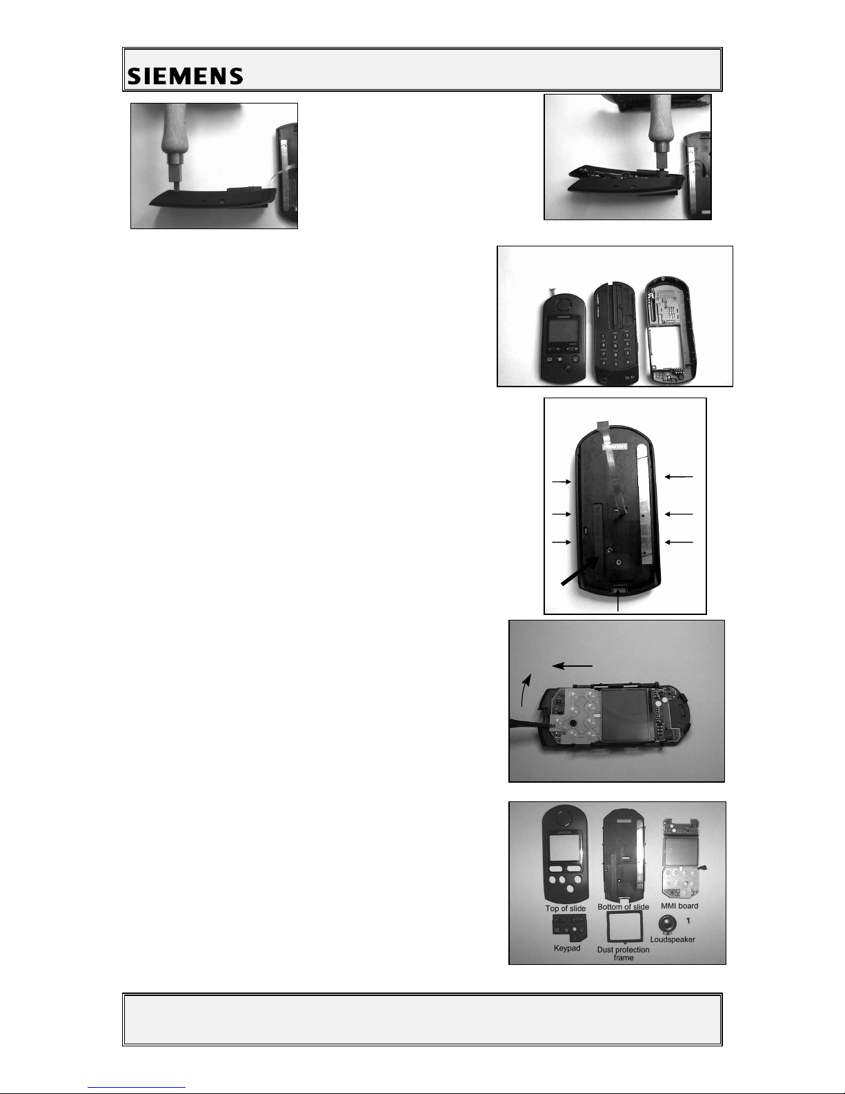
1. Now de ach he flexible cable
from he plug on he con rol
module by undoing he re aining
clip on he plug and hen pulling
he cable ou .
1. Now you have separa ed he
hree major par s of he elephone
a) Slide, b) Top of base, c) Bo om of base
4.2.3 Disassembling the Slide
1. Unscrew he coun ersunk-head screw (A)
2. Nex , release he lower ca ch (B)
. Then release he six la eral ca ches (1-6 )
1. Af er releasing he ca ches, remove he bo om par of he
slide.
2. Now remove he MMI board from he bo om par of he
slide by raising he board (1.) and pushing i oward he
keypad (2.).
Attention: Do no crease or damage he flexible cable
on he lower side of he MMI.
1. Finally, remove he dus pro ec ion frame, he keypad
ma and he loudspeaker from he op par of he slide.
You now have disassembled he slide comple ely.
1.
2.
a) b) c)
A B
4 1
5 2
6 3

Private Communication Systems
Mobile Phones
Service Manual SL10 V1.1 PN MP ST
R. Fleuren
Sm_sl10_lvl2_v11.doc Page 9 of 22 05/98
4.2.4 Disassembling the Top Part of the Base
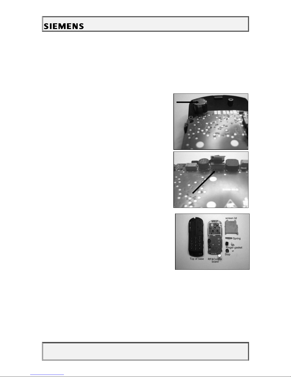
1. Firs remove he microphone holder and he flexible microphone cable a ached o i from
he microphone housing.
1. Then de ach he flexible keypad cable from he ZIF-
plug (ZIF=Zero Inser ion Force).
To do so, please firs open he re aining clip and pull
ou he cable af erwards.
2. Remove he ringer gaske .
. Now remove he four orx fla -head screws on he
screen lid and he wo orx coun ersunk-head screws on
he side of he microphone.
1. Now remove he con rol module and he screen lid.
2. Finally, remove he microphone.
Now you comple ed disassembling he Top of base.

Private Communication Systems
Mobile Phones
Service Manual SL10 V1.1 PN MP ST
R. Fleuren
Sm_sl10_lvl2_v11.doc Page 10 of 22 05/98
4.2.5 Disassembling the Bottom Part of the Base
1. Firs remove he ba ery basepla e.
2. Then remove he ba ery con ac s rip.
. Finally, remove he charge con ac s.
4.3 Assembling the SL10
Caution!
Inside he elephone here are hree flexible cables, which are very sensi ive o any kind of
mechanical damage. Please be careful during all he assembling process no o damage hem
e.g. by bending or snapping.
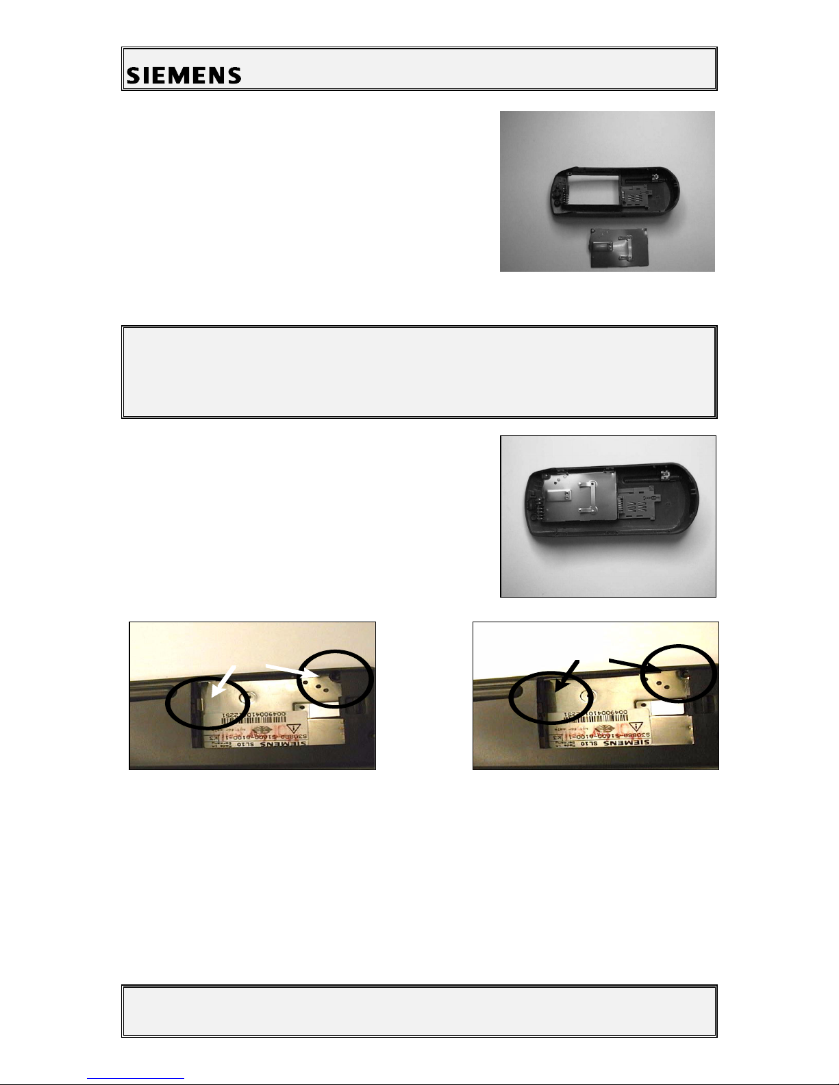
4.3.1 Assembling the Bottom Part of the Base
Inser he charge con ac s, he ba ery con ac s rip and he
ba ery basepla e.
Make sure ha you inser he basepla e in he righ way,
because o herwise you will have o reopen he phone
again (See figures below).
N o t o .k .
o .k .
Other manuals for SL10
6
Table of contents
Other Siemens Cell Phone manuals

Siemens
Siemens HiPath C10 User manual

Siemens
Siemens CX65 User manual

Siemens
Siemens M35i User manual

Siemens
Siemens SL10 User manual

Siemens
Siemens S65 User manual

Siemens
Siemens CX75 Setup guide

Siemens
Siemens SIMATIC S7 CP340 Operating instructions

Siemens
Siemens SL65 Setup guide

Siemens
Siemens S40 User manual

Siemens
Siemens A70 User manual

Siemens
Siemens A62 User manual

Siemens
Siemens CF75 User manual

Siemens
Siemens Xelibri X6 User manual

Siemens
Siemens S46 User manual

Siemens
Siemens SL45i User manual

Siemens
Siemens SK65 User manual

Siemens
Siemens ME75 User manual

Siemens
Siemens CFX65 Setup guide

Siemens
Siemens 1168 User manual

Siemens
Siemens CF62 User manual