
Showco Spot 250 S User manual


Please read over this manual before operation the light
1) Open the box and checking----------------------------------------
Safety instructions--------------------------------------------------
-----------------------------------------
----------------------------------------------------------
Install the lamp ------------------------------------------------------
Installing the projector ---------------------------------------------
Control connections ------------------------------------------------
Control Board Operation-------------------------------------------
--------------------------------
Specification---------------------------------------------------------
-------------------------------------------------------------
---------------------------------------------------
Structure of the fixture----------------------------------------------
-------------------------------------------
---------------------------------------------
--------------------------------------------------------------
------------------------------------------------------
Page 1
2) Page 1
3) Page 2
4) Page 3
5) Page 4
6) Page 5
7) Page 5
8) Page 6
9) DMX512 Channel function setting Page 8
10) Page 16
11) Page 16
12) Electrical diagram Page 17
13) Page 18
14) Commen faulty maintain Page 19
15) Component antitheses Page 20
16) Maintain Page 21
17) Announcement Page 21
Operating determinations
Beampath
Dimensions
www.carlosmendoza.com.mx

1
1. Open the box and checking
Congratulations on choosing our products! Please carefully read this instruction manual in its
entirety and keep it well for using reference. This manual contained about the installation and the
relative using information of this products. Please according to this manual's relative speaking when
using this equipment.
This equipment was made of new style, high intensity plastic and cast aluminium. It fully
shows the modem times light characteristic with beauty structure. And it was made according to CE
standard. Fully up the international standard of DMX512 agreement. Master or slave in phase
control. Can be use in large entertainment, theater, performing and playing hall, etc.
When receiving this product please carefully bring and put; and check that whether this
equipment has been damaged or not during transportation. And please also check the following
thing was enclosed:
Signal line ----------------------- 1 PC Safety string -----------------------1 PC
User Manual-----------------------1 PC Hanging bracket-------------------2 PCS
2. Safety instructions
Every person involved withinstallation and maintenance of this device have to:
- be qualilfied
- follow the instructions of this manual
CAUTION:
ØKeep this device away from rain and moisture!
ØUnplug mains lead before opening the housing!
ØFOR YOUR OWN SAFETY, PLEASE READ THISUSER MANUALCAREFULLY
ØBEFORE YOU INITIALSTART -UP!
ØBe careful with your operations.
ØWith a high voltage you can suffer a dangerous electric shock when touching the
wires!
ØThis device has left our premises in absolutely perfect condition. In order to maintain
this condition and to ensure a safe operation, it is absolutely necessary for the user to
follow the safety instructions and warning notes writtenin this manual.
Important:
ØThe manufacturer will not accept liability for any resulting damages caused by the non-
observance of this manual or any unauthorized modification to the device.
ØPlease consider that damages caused by manual modifications to the device are not
subject to warranty.
ØNever let the power-cord come into contact with other cables! Handle the power-cord
and all connections with the mains with particular caution!
ØMake sure that the available voltage is not higher than stated on the rear panel.
ØAlways plug in the power plug least. Make sure that the power-switch is set to OFF-
position before you connect the device to the mains. Thepower-plug hasto be
accessable after installing the device.
ØMake sure that the power-cord isnever crimped or damaged by sharp edges. Check the
device and the powercord from time to time.
www.carlosmendoza.com.mx

2
Øby the plug. Never pull out the plug by tugging the power-cord.
ØThis devicefalls underprotection classI. Thereforeit isessential toconnect the
yellow/green conductorto earth.
ØThe electric connection, repairs and servicing must be carried out by a qualified
employee.
ØDo not connect this device to a dimmer pack.
ØDo not switch the fixture on and off in short intervals as this would reduce the lamp s
life.
ØDuring the initial start-up some smoke or smell may arise. This is a normal process and
does not necessarily mean that the device is defective.
ØDo not touch the device s housing bare hands during its operation (housing becomes hot)!
ØFor replacement use lamps and fuses of same type and rating only.
CAUTION :
EYE DAMAGES !
Avoid looking directly into the light source(meant especially for epileptics) !
Ø
Ø
Ø
Ø
Ø
Ø
Ø
Ø
Ø
Ø
Ø
3. Operating determinations
This device is a moving-head spot for creating decorative effects and wasdesigned for
indoor use only.
If the device has been exposed to drastic temperature fluctuation (e.g. After transport-
ation), do not switch it onimmediately. The arising condensation water might damage
your device. Leave the device switched offuntil it has reached room temperature.
Never run the device without lamp!
Do not shake the device.Avoid brute force when installing or operating thedevice.
Never lift the fixture by holding it at the projector-head,as the mechanics may be
damaged. Always hold thefixture at the transport handles.
When choosing the installation-spot, please make sure that the device is not exposed to
extreme heat, moistureor dust.There should not be any cables lying around.You
endanger yourown and the safety of others!
The minimum distance between light-output and the illuminated surface must be more
than 2 meters.
Make sure that the area below the installation place is blocked when rigging, derigging
or servicing the fixture.Always fix the fixture with an appropriate safety-rope.Fix the
safety-rope atthe correct holes only.
Only operate the fixture after having checked that the housing is firmly closed and all
screws are tightly fastened.
The lamp must never be ignited if the objective-lens or any housing-cover is open, as
discharge lampsmayexplose and emit a high ultraviolet radiation, which may cause
burns.
The maximum ambient temperature ta = 40 must never be exceeded. Otherwise, the
lamp is switched off andthe fixture is out of operation for 5 minutes.
www.carlosmendoza.com.mx

A
B
C
Adjust lamp position by
turning screws A,B and C
ONLY USE REPLACEMENT
LAMP : MSD 250
4
Ø 5. Install the lamp
ØDisassemble the 2pcs M4 plain screws from the cover for change lamp at the back of light, then
take the cover for change lamp and lamp out of product together.
ØPut the lamp into lamp holder.
ØDon't use your hand to touch the mirror cover of lamp during installation. Please use soft cloth
to clean if you touch it by chance to provide the light effect.
ØPut in the cover for change lamp carefully and screw 2pcs M4 screws firmly.
Lamp adjust
Lamp seat
Lamp
NOTE: When fitting the lamp position it with the little bubble vertically (either upwards or
downwards) as shown in the diagram above. Do not position it horizontally. Close the
access hatch carefully and re-tighten the 3 screws. To optimize light output it will be
necessary to adjust the lamp alignment to obtain an even distribution of light within the
beam. The three screws (marked A, B, and C) may be gently turned to center the lamp
within the reflector. The projector should be switched on with the shutter open and the beam
focused to do this, it is also advisable to allow the lamp 5 minutes to come up to full
brightness before starting to align it. Note: the three screws will only need a small
adjustment to centre the lamp, do not try to unscrew them completely.
Back panel
of lamp holder
Back panel
of lamp holder
www.carlosmendoza.com.mx

214mm
170mm
214mm
5
6. Installing the projector
The projector should be mounted via its bracket using two M12 bolt.
The bracket itself attaches to the underside of the projector with four(2)M8x25 bolts
provided.
Always ensure that the projector is firmly anchored to avoid vibration and slipping whilst
operating.
Always ensure that the structure to which you are attaching the projector is secure and is
able to support a weight of 19.4 Kg for each equipment.
For safety the projector should have a secondary fixing with a safety chain through the
holes on the underside of the unit.
WARNING: The projector should NEVER be lifted or carried by the yoke.
BRACKET
Pass safety fixing
through these holes
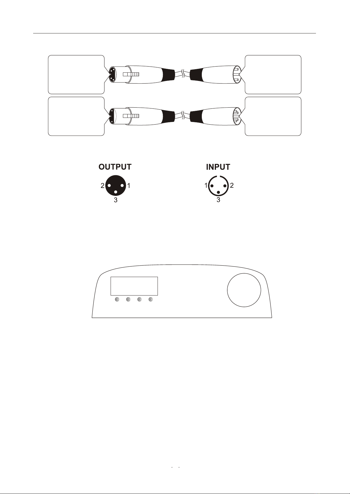
ØConnect the XLR-XLR control line from the DMX output of controller to DMX input of
each product and connect the DMX output of the first one to the DMX input of the
second one. Connect all products in this way. Then use the attached circle plug to
connect the signal output of last machine like picture show:
ØNote: Please remember the signal output of last machine must connect the attached circle
plug. The circle plug connect a 120 resistance between 2 feet and 3 feet canon plug.
The signal reflects phenomena can be avoided by using circle plug during DMX 512
signal transfer.
ØThe product use 3 feet XLR plug. If the controller you use is 5 feet XLR plug, you must
use a interchange line from 5 feet to 3 feet as following picture:
7. Control connections
Console singal input Output and input connect together Output and input connect together
POWER IN MIC
OUT DMX IN
ON
OFF
AUX POWER IN MIC
OUT DMX IN
ON
OFF
AUX POWER IN MIC
OUT DMX IN
ON
OFF
AUX
Light 1 Lignt N
Light 2
Terminator
www.carlosmendoza.com.mx
DOWN
ENTER UPMENU
6
5Pins canon( )plug
Pin 1: GND(SCREEN)
Pin 2: Signal(-)
Pin 3: Signal(+)
Pin 4: N/C
Pin 5: N/C
3
Pin 1: GND(SCREEN)
Pin 2: Signal(-)
Pin 3: Signal(+)
Pins canon(socket)
5Pins canon(socket)
Pin 1: GND(SCREEN)
Pin 2: Signal(-)
Pin 3: Signal(+)
Pin 4: N/C
Pin 5: N/C
3 plug
Pin 1: GND(SCREEN)
Pin 2: Signal(-)
Pin 3: Signal(+)
Pins canon( )
The transform of the controller line of 3 pins and 5 pins (plug and socket)
Pin 1: Screen
Pin 2: Signal -
Pin 3: Signal +
3 pins canon plug of DMX512 connect circuit
8.1 Control board operation way:
1.Select workingmode bypressing MENU.
2.Press ENTERto confirmthe selection.
3.Press UP and DOWN to selectworking condition.
4.Press ENTERto confirmthe selection.
8. Control Board Operation
www.carlosmendoza.com.mx

7
8.2 Function Table:
8-Channels
select:Advanced
1-Address
select:001
2-Reset
select:Yes
2-Reset
select:No
3-Operation
select:DMAX512
3-Operation
select:AUTO1
3-Operation
select:Micro1
3-Operation
select:SLAVE
3-Operation
select:Random
3-Operation
select:AUTO2
3-Operation
select:Micro2
4-Display
select:Bright
4-Display
select:60 close
5-Plane
select:Normal
5-Plane
select:Reverse
6-Tilt
select:normal
6-Tilt
select:Reverse
7-Color
select:Step
7-Color
select:Line
8-Channels
select:Basic
1-Address
2-Reset
3-Operation
4-Display
5-Plane
6-Tilt
7-Color
8-Channels
9-Info
Mode Effect/Working mode Effect description
Address setting
NO Reset
Reset
DMX512 mode
Automatic mode1
Music activemode 1
Slave mode
Random mode
Automatic mode2
Music activemode 2
60 Secondsclose
Bright
Pan normal
Pan reverse
Tiltnormal
Tiltreverse
Color wheelon step
Color wheelon line
System version
Basic Channel mode
Advanced Channel mode
www.carlosmendoza.com.mx

Focus
8
PAN
TILT
PAN movementfine adjust
TILT movementfine adjust
Scan speedadjust
Color wheel
Strobe
Dimmer
CHANNEL
FUNCTION
Gobo wheel& Gobooshake
Gobo rotation
Automatic &Reset
Effect
Prism
1
2
3
4
5
6
7
8
9
10
11
12
13
14
9. DMX512 Channel function setting
Function under MASTER Mode
Function under BASIC Mode
Focus
PAN
TILT
Color wheel
Strobe
Dimmer
CHANNEL
FUNCTION
Gobo wheel& Gobooshake
Gobo rotation
Automatic &Reset
Prism
1
2
3
4
5
6
7
8
9
10
www.carlosmendoza.com.mx

Table of contents
Popular Light Fixture manuals by other brands

Emos
Emos CLASSIC ZY1431T manual

Westinghouse
Westinghouse Outdoor Lighting Fixture owner's manual

Hedler
Hedler C 12 silent Operation manual
Blizzard Lighting
Blizzard Lighting Puck: CSI manual

Energetic Lighting
Energetic Lighting ELYSL-5004 Series installation instructions

Lightmaxx
Lightmaxx Shaft 5R user manual


Cooper Lighting
Cooper Lighting Halo L3232E Specification sheet

Stageline
Stageline ODW-2410RGBW instruction manual

Light Sky
Light Sky Tornado Series user manual

Lightolier
Lightolier Paralyte 2424 PLA2G9LS26U specification

Lightolier
Lightolier Lytespan 83ED17S specification

Lightolier
Lightolier Calculite CS8226 specification