SafeWaze 019-11003 User manual

WARNING
This product is part of a personal fall arrest, work positioning, or rescue system. The manufacturer’s instructions must be provided to
users of this equipment. The user must follow the manufacturer’s instructions for each component of the system. The user must read and
understand these instructions before using this equipment. Manufacturer’s instructions must be followed for proper use and maintenance
of this equipment. Alterations to this product, misuse of this product, or failure to follow instructions may result in serious injury or death.
IMPORTANT
Questions regarding the use, care, or suitability of this equipment for your application? Contact SafeWaze.
IMPORTANT
Record initial usage of product on Page 2, and Page 15. Competent Person inspections are required to be documented in the Inspection
Log Table on Page 15.
019-11003
Tripod with 65’ Material Winch
and 65’ 3-Way
2057
User Manual
V1.0 2020 Copyright SafeWaze Page 1

TABLE OF CONTENTS
1 INTRODUCTION....................................................................................3
2 APPLICABLE SAFETY STANDARDS....................................................3
3 WORKER CLASSIFICATIONS...............................................................3
4 PRODUCT SPECIFIC APPLICATIONS..................................................4
5 LIMITATIONS..........................................................................................4
6 COMPATIBILITY OF CONNECTIONS ...................................................5
7 MAKING CONNECTIONS......................................................................6
8 COMPONENTS AND SPECIFICATIONS...............................................7
9 INSTALLATION AND USE....................................................................8-12
10 OPERATION........................................................................................12-13
11 INSPECTION.......................................................................................13-15
12 INSPECTION LOG................................................................................15
13 SAFETY INFORMATION.....................................................................16-17
14 LABELS.................................................................................................17
Do not throw away these instructions!
Read and understand these instructions before using equipment!
User Information
Date of First Use:
Serial#:
Trainer:
User:
User Manual
V1.0 2020 Copyright SafeWaze Page 2

INTRODUCTION
Thank you for purchasing the SafeWaze 019-11003 Conned Space System. This manual must be
read and understood in its entirety, and used as part of an employee training program as required by
OSHA or any applicable state agency.
This manual and any other instructional material must be available to the user of the equipment.
The user must understand how to safely and eectively use the 019-11003, and all fall protection
equipment used in conjuction with the 019-11003.
The 019-11003 Conned Space System is designed primarily for workers entering and working in
conned space environments. OSHA denes conned space as any space with limited openings for
entry and exit, is large enough for a worker to enter bodily and perform work, and is not designed for
continuous worker occupancy.
Conned spaces include but are not limited to, utility manholes, silos, undergound utility vaults,
storage containers, pits, and pipelines.
The 019-11003 Conned Space Tripod serves as the support element for entry/egress into conned
spaces, and also the rescue/evacuation of workers if necessary. It can also provide anchorage for fall
protection, work postioning, and personnel riding systems.
APPLICABLE SAFETY STANDARDS
When used according to instructions, this product meets or exceeds all applicable OSHA 1926.502
OSHA 1910.146, OSHA 1926.21, ANSI Z359.1-2007, ANSI Z117.1-2009, ANSI Z359.14-2014,
ANSI A10.32-2012 standards for fall protection. Applicable standards and regulations depend on the
type of work being done, and also might include state-specic regulations. Refer to local, state, and
federal (OSHA) requirements for additional information concerning the governing of occupational
safety regarding Personal Fall Arrest Systems (PFAS).
Worker Classifications
Understand the denitions of those who work in proximity of or may be
exposed to fall hazards.
Qualied Person: A person with an accredidated degree or certication, and with extensive
experience or sucient professional standing, who is considered procient in planning and reviewing
the conformity of fall protection and rescue systems.
Competent Person: A highly trained and experienced person who is assigned by the employer to
be responsible for all elements of a fall safety program, including, but not limited to, its regulation,
management, and application. A person who is procient in identifying existing and predictable
hazards, and who has the authority to stop work in order to eliminate hazards.
Authorized Person: A person who is assigned by their employer to work around or be subject to
potential or existing fall hazards.
It is the responsibility of a Qualied or Competent person to supervise the job site and
ensure safety regulations are complied with.
User Manual
V1.0 2020 Copyright SafeWaze Page 3

Product Specific Applications
Rescue / Conned Space: The 019-11003 Conned Space System may be used in both Conned
Space and Rescue applications. Rescue systems function to safely remove a worker from a conned
space environment or after exposed to a fall. There are various congurations of rescue systems
depending on the type of rescue required. Structure must withstand loads applied in the directions
permitted by the system of at least 3,000 lbs. No free fall is permitted. Applicable D-rings are dorsal,
chest, and shoulder.
Lanyard Length
(6’ Total)
Deceleration
distance (4’ total)
Height of harness
dorsal D-ring from
worker’s feet
(6’ total)
Safety factor
(2’ total)
Required
distance
from
Anchorage
(18’ total)
Fall Clearance: There must be sucient clearance below the anchorage connector to arrest a fall
before the user strikes the ground or an obstruction. When calculating fall clearance, account for a
MINIMUM 2’ safety factor, deceleration distance, user height, length of lanyard/SRL, and all other
applicable factors. (See Figure 1)
Limitations
Fall Clearance Diagram
***Diagram shown is an example
fall clearance calculation ONLY. For all applications: worker weight capacity range
(including all clothing, tools, and equipment) is 130-310 lbs
FIGURE 1
User Manual
V1.0 2020 Copyright SafeWaze Page 4

Swing Falls: Prior to installation or use, make considerations for eliminating or minimizing all swing
fall hazards. Swing falls occur when the anchor is not directly above the location where a fall occurs.
Always work as close to in line with the anchor point as possible. Swing falls signicantly increase
the likelihood of serious injury or death in the event of a fall. (See Figure 2)
A
FALL-ARREST
S
W
I
N
G
F
A
L
L
COMPATIBILITY OF CONNECTORS
Connectors are compatible with connecting elements when they have been designed to work together
in such a way that their sizes and shapes do not cause their gate mechanisms to inadvertently
open regardless of how they become oriented. Connectors (hooks, carabiners, and D-rings) must
be capable of supporting at least 5,000 lbs. (22.2 kN). Connectors must be compatible with the
anchorage or other system components (see Figure 4). Do not use equipment that is not compatible.
Non- compatible connectors may unintentionally disengage (see Figure 3). Connectors must be
compatible in size, shape, and strength. Self-locking snap hooks and carabiners are required by
ANSI Z359 and OSHA guidelines. Contact SafeWaze if you have any questions about compatibility.
FIGURE 3 - UNINTENTIONAL DISENGAGEMENT
Non-compliant part
Using a connector that is undersized or irregular in shape (1) to connect a snap hook or carabiner
could allow the connector to force open the gate of the snap hook or carabiner. When force is applied,
the gate of the hook or carabiner presses against the non-compliant part (2) and forces open the gate
(3). This allows the snap hook or carabiner to disengage (4) from the connection point.
3 - gate opens
2 - gate presses
against
non-complaint
part
4 - and parts disengage.
1 -
NOTE: SOME SPECIALITY CONNECTORS HAVE ADDITIONAL REQUIREMENTS.
CONTACT SAFEWAZE WITH QUESTIONS.
FIGURE 2
User Manual
V1.0 2020 Copyright SafeWaze Page 5

User Manual
V1.0 2020 Copyright SafeWaze Page 6
MAKING CONNECTIONS
Snap hooks and carabiners used with this equipment must be double locking and/or twist lock.
Ensure all connections are compatible in size, shape and strength. Do not use equipment that is not
compatible. Ensure all connectors are fully closed and locked.
SafeWaze connectors (snap hooks and carabiners) are designed to be used only as specied in each
product’s user’s instructions. See gure 4 for examples of inappropriate connections. Do not connect
snap hooks and carabiners:
• To a D-ring to which another connector is attached.
• In a manner that would result in a load on the gate (with the exception of tie back hooks).
• NOTE: Large snap hooks must not be connected to objects which will result in a load on the
gate if the hook twists or rotates, unless the snap hook complies with ANSI Z359.1-2007 or ANSI
Z359.12 and is equipped with a 3,600 lb (16 kN) gate. Check the marking on your snap hook to
verify its compatibility.
FIGURE 4 - INAPPROPRIATE CONNECTIONS
• In a false engagement, where features that protrude from the snap hook or carabiner catch on the
anchor, and without visual conrmation seems to be fully engaged to the anchor point.
• To each other.
• By wrapping the web lifeline around an anchor and securing to lifeline except as allowed for Tie
Back models.
• To any object which is shaped or sized in a way that the snap hook or carabiner will not close and
lock, or that roll-out could occur.
• In a manner that does not allow the connector to align properly while under load.

Components and Specifications
Tripod Safety Chain
Pulleys
019-11003
Tripod with 65’ Material Winch
and 65’ 3-Way
Adjustable Legs
3-Way
Material Winch
Tripod
Interior Headroom 81 in (2057.4 mm)
Distance Between Feet 61 in (1549.4 mm)
Max Diameter Hole 44 in (1117.6 mm)
Working Load 350 lbs (158.76 kg)
Overall Height 84 in (2133.6 mm)
Storage Length 65 in (1651 mm)
Outside Head Diameter 17 in (431.8 mm)
Leg Adjustment Increments 6 in (152.4 mm)
Weight 50 lbs (22.68 kg)
Length/Type 65 ft (19.81 m) Galvanized Steel
Breaking Strength 4200 lbs (1905.08 kg)
Maximum Work Load 310 lbs (140.61 kg)
Minimum Work Load 110 lbs (49.9 kg)
Locking Speed 4 - 5 ft/sec (1.22 - 1.52 m/sec)
Stopping Distance < 54 in (1371.6 mm)
Speed Rescue Mode Approximate 20 ft/min (6.1 m/min)
Gear Ratio 5.5:1
Mechanical Advantage 29 lbs (13.15 kg)
Weight 35 lbs (15.88 kg)
3-Way
Cable 0.19 in (4.83 mm) steel
Weight 32 lbs (14.52 kg)
Lifting Capacity 600 lbs (272.16 kg)
Size 11 in x 8 in (279.4 mm x 203.2 mm)
Handle Length 14 in (355.6 mm)
User Manual
V1.0 2020 Copyright SafeWaze Page 7

Installation and Use
Step 1: Remove tripod from tripod storage/carrying bag.
Step 2: Tripod must be mounted on a stable level surface for each leg, when positioned over
opening, with a Maximum Installation Diameter of 44 inches. Lift tripod to upright position. Press
locking pin above each leg in the tripod head and pull leg away from center point until locking pin
locks into place. Repeat with the remaining legs. (See Image 1)
Step 3: Remove Locking Pins above foot of tripod legs and extend legs to desired height. Re-insert
locking pin at desired height, (See Image 2) and connect safety chains to bottom of tripod legs.
Remove excess slack in the safety chain by adjusting the position of the twist link.
Step 4: This step decribes actions to be taken if attaching / installing a Safewaze 3-Way Retractable,
Material Winch, or Personnel Winch onto the tripod via mounting to one of the tripod legs. This step
must be performed in order to ensure proper routing of component cables through the top of the
tripod. Remove Cotter Pins, Pulley Housing, and pulleys from the top of tripod. (See Image 3 & 4)
Image 1
Image 2
Image 3 Image 4
Locking Pin
Locking Pin
Cotter Pin
Pulley
Pulley Housing Top of Tripod
(With pulleys removed)
User Manual
V1.0 2020 Copyright SafeWaze Page 8

Step 5: Install the Material Winch onto the tripod by placing the winch onto the pre-installed xture
plate of the tripod. Seat the hook of the winch bracket plate onto the cross bar of the tripod bracket.
(See Images 5 & 6)
Step 6: Rotate the winch assembly forward to allow for installation of the locking pin into the
pre-drilled holes in the winch bracket plate and the tripod bracket. (See Images 7 & 8)
Image 5
Image 7
Image 6
Image 8
Winch Bracket
Plate
Cross Bar of the
Tripod Bracket
Insert Locking
Pin
Hook of Winch Bracket
Plate seated onto
crossbar of Tripod Bracket
Tripod Fixture
Plate
Rotate Forward
Winch Bracket
Plate Hook
Winch
Step 7: Rotate the handle of the winch counter-clock wise to release the steel cable. Continue to
release the cable until enough length allows for the snap hook to be dropped down through the top of
the tripod. (See Image 9 & 10)
Image 9 Image 10
User Manual
V1.0 2020 Copyright SafeWaze Page 9
Step 7: Extend cable and route through top of tripod. To extend the cable from the unit, pull the
function switch button out, and then pull the crank handle base outward from the 3-Way Housing.
(See Image 15a) This places the 3-way unit into it’s Self Retracting Device conguration. Pull out the
required amount of cable to drop through the head assembly of the tripod. Pulling out once again on
the function switch and pushing the base of the crank handle assembly inward places the unit into
Rescue/Recovery mode.(See Image 15b) Drape the cable over the top of the tripod and slide the
snap hook down through the opening in the top of the tripod where the pulley (previously removed in
Step 4) is normally seated. (See Image 16)
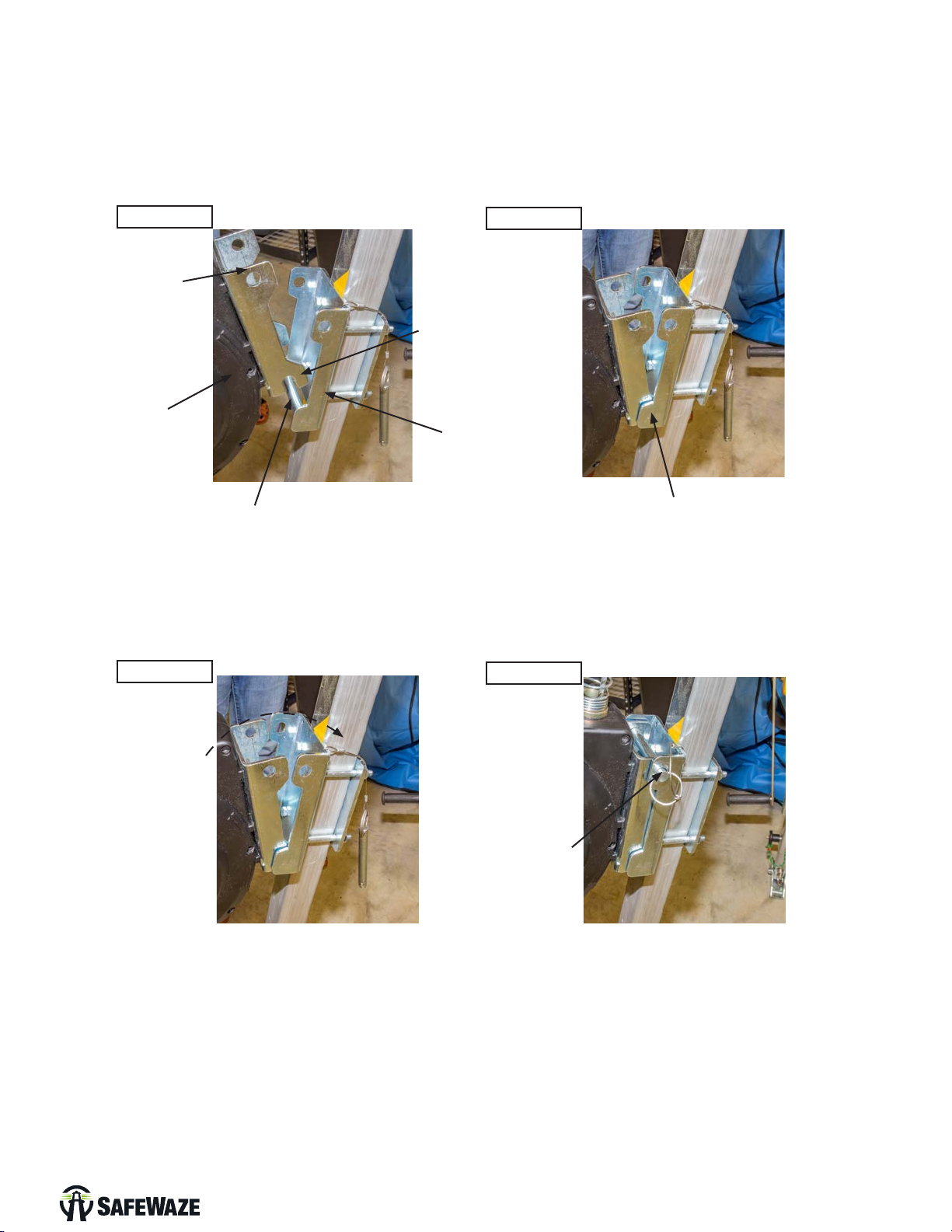
Step 5: Install the 3-Way onto the tripod by placing the 3-Way onto the pre-installed xture plate of
the tripod. Seat the hook of the 3-Way bracket plate onto the cross bar of the tripod bracket.
(See Images 5 & 6)
Step 6: Rotate the winch assembly forward to allow for installation of the locking pin into the
pre-drilled holes in the winch bracket plate and the tripod bracket. (See Images 13 & 14)
Image 11
Image 13
Image 12
Image 14
3-Way Bracket
Plate
Cross Bar of the
Tripod Bracket
Insert Locking
Pin
Hook of 3-Way Bracket
Plate seated onto
crossbar of Tripod Bracket
Tripod Fixture
Plate
Rotate Forward
Winch Bracket
Plate Hook
3-Way
User Manual
V1.0 2020 Copyright SafeWaze Page 10
Table of contents
Languages:
Other SafeWaze Camera Accessories manuals

Popular Camera Accessories manuals by other brands

Viltrox
Viltrox EF-NEX Mount instructions

Calumet
Calumet 7100 Series CK7114 operating instructions

Ropox
Ropox 4Single Series User manual and installation instructions

Cambo
Cambo Wide DS Digital Series Main operating instructions

Samsung
Samsung SHG-120 Specification sheet

Ryobi
Ryobi BPL-1820 Owner's operating manual


