r.LiNK CI-RL3-C3D User manual

Version 11.09.2019 HW:CAM (V98) / (V20) CI-RL3-C3D
r.LiNK Video inserter
CI-RL3-C3D
Compatible with
Alfa Romeo vehicles
with Connect Radio and 6.5 inch monitor
or Connect 3D navigation and 8.8 inch monitor
Video-inserter for one rear-view camera and two additional video inputs
Product features
Video-inserter for factory-infotainment systems
CVBS Input for one rear-view camera
2 CVBS Video-inputs for after-market Video sources (e.g. USB-Player, DVB-T2
Tuner)
Automatic switching to rear-view camera input on engagement of the reverse gear
Activatable parking guide lines for rear-view camera (not available for all vehicles)
Video-in-motion (ONLY for connected video-sources)
Video-inputs NTSC compatible

Version 11.09.2019 HW:CAM (V98) / (V20) CI-RL3-C3D
Page2
Contents
1. Prior to installation
1.1. Delivery contents
1.2. Checking the compatibility of vehicle and accessories
1.3. Boxes and connectors –video interface
1.4. Settings of the 8 Dip switches (black)
1.4.1. Enabling the interface’s video inputs (dip 2-3)
1.4.2. Rear-view camera setting (dip 5)
1.4.3. Activating the guide lines (dip6)
1.4.4. Monitor selection (Dip 7 and8)
1.5. Settings of the 4 Dip switches (CAN function –red)
2. Installation
2.1. Place of installation
2.2. Connection schema
2.3. Connection to factory head unit and monitor
2.3.1. Connection to the picture signal cable –
2.3.2. Connection to Quadlock - CAN
2.4. Connection of video-sources
2.4.1. Audio insertion
2.4.2. After-market rear-view camera
2.4.2.1. Case 1: Interface receives the reverse gear signal
2.4.2.2. Case 2Interface does not receive the reverse gear signal
2.5. Connecting video-interface and external keypad
2.6. Picture settings and guide lines
3. Interface operation
3.1. By factory infotainment button
3.2. By keypad
4. Specifications
5. FAQ –Trouble Shooting-Interface functions

Version 11.09.2019 HW:CAM (V98) / (V20) CI-RL3-C3D
Page3
Legal Information
By law, watching moving pictures while driving is prohibited, the driver must not be
distracted. We do not accept any liability for material damage or personal injury resulting,
directly or indirectly, from installation or operation of this product. Apart from using this
product in an unmoved vehicle, it should only be used to display fixed menus or rear-view-
camera video when the vehicle is moving (for example the MP3 menu for DVD upgrades).
Changes/updates of the vehicle’s software can cause malfunctions of the interface. Up to
one year after purchase we offer free software-updates for our interfaces. To receive a free
update, the interface has to be sent in at own cost. Wages for de-and reinstallation and
other expenditures involved with the software-updates will not be refunded.
1. Prior to installation
Read the manual prior to installation. Technical knowledge is necessary for installation. The
video interface’s place of installation must be free of moisture and away from heat sources.
Before the final installation in the vehicle of the video sources, we recommend a test-run
to ensure the compatibility of vehicle and interface. Due to changes in the production of
the vehicle manufacturer there’s always a possibility of incompatibility.
1.1. Delivery contents
'ahmad@fosp.cn'
Take down the serial number of the interface and store this manual for support
purposes: ____________________

Version 11.09.2019 HW:CAM (V98) / (V20) CI-RL3-C3D
Page4
Requirements
Brand
Compatible vehicles
Compatible systems
Alfa Romeo
Giulia (952) since model year 2016
Stelvio (949) since model year 2017
Connect Radio with 6.5 inch monitor and
Connect 3D navigation with 8.8 inch monitor
Limitations
Video only The interface inserts ONLY video signals into the infotainment. For inserting
Audio signals either the possibly existing factory audio-AUX-input or a FM-
modulator can be used. If 2 audio sources shall be connected to the
infotainment, an additional electronic is necessary to switch them.
Factory rear-view camera Automatically switching-back from inserted video to factory rear-view camera is
only possible while the reverse gear is engaged. To delay the switch-back an
additional electronic part is required.
Video input signal Only NTSC compatible.
Guide lines If the interface does not receive the required information from the vehicle CAN-
bus, the guide-lines will not be supported.
1.2. Checking the compatibility of vehicle and accessories

Version 11.09.2019 HW:CAM (V98) / (V20) CI-RL3-C3D
Page5
1.3. Boxes and connectors –video interface
The video-interface converts the video signals of connected after-market sources in a factory
monitor compatible picture signal which is inserted in the factory monitor, by using separate
trigger options. Further it reads the vehicle’s digital signals out of the vehicle’s CAN-bus and
converts them for the video interface.
1.4. Settings of the 8 Dip switches (black)
Some settings have to be selected by the dip-switches of the
video interface.
Dip position down is ON and position up is OFF.
In case of a non-optimal displayed picture with the mentioned dip settings of dip7 and dip8,
we recommend to try each other possible dip switch combination.
See the following chapters for detailed information.
After each Dip-switch-change a power-reset of the Can-box has to be performed!
See the following chapters for detailed information.
Dip
Function
ON (down)
OFF (up)
1
No function
set to OFF
2
CVBS Video 1-input
enabled
disabled
3
CVBS Video 2-input
enabled
disabled
4
No function
set to OFF
5
Rear-view cam type
after-market
factory or none
6
Guide lines
guide lines enabled
guide lines disabled
7
Monitor-specific
adjustments
6.5inch monitor: dip7OFF / dip8 ON
8.8inch high resolution monitor: dip7ON / dip8 OFF
8.8inch lower resolution monitor: dip7OFF / dip8 OFF
8

Version 11.09.2019 HW:CAM (V98) / (V20) CI-RL3-C3D
Page6
1.4.1. Enabling the interface’s video inputs (dip 2-3)
Only by dip switches enabled video inputs can be accessed by switching through the
interface’s video sources. It is recommended to enable only the required inputs. Disabled
inputs will be skipped while switching through the video interfaces inputs.
Note: Dip 1 and 4 are out of function and have to be set to OFF!
1.4.2. Rear-view camera setting (dip5)
If set to OFF, the interface switches to factory picture while the reverse gear is engaged to
display factory rear-view camera or factory optical park system picture.
If set to ON, the interface switches to its rear-view camera input while the reverse gear is
engaged.
1.4.3. Activating the guide lines (dip6)
If set to ON, the guide-lines will be shown on the display.
If set to OFF, the guide lines won’t be visible on the display.
Note:If there is no communication between interface and the vehicle`s CAN-bus (several
vehicles aren’t compatible), the reverse gear guide-lines can`t be shown during the vehicle’s
operation, even if they once appear after having switched the system to powerless!
1.4.4. Monitor selection (dip7 and 8)
Dips 7-8 customize the monitor-specific video settings. For the according monitor, use the
dipswitch combinations shown in the table below. Sometimes the mentioned settings vary
even within head units of the same version, caused by different monitor specifications. In
case of a non-optimal displayed picture with the mentioned dip settings, we recommend to
try each other possible dip switch combination of dip7 and dip8 while a working video
source is connected to the chosen input of the interface. One of the 4 combinations will
show the best picture size and quality (some may give no picture). It is possible to first hot
plug through the dip combinations. If there is no change of picture visible after trying all 4
options, retry and disconnect the 6pin plug at the interface box between every change of the
dip setting.
Empirical value:
Size of monitor
Dip 7
Dip8
6.5inch monitor
OFF
ON
8.8 Zoll high resolution monitor
ON
OFF
8.8 Zoll lower resolution monitor
OFF
OFF

Version 11.09.2019 HW:CAM (V98) / (V20) CI-RL3-C3D
Page7
1.5. Settings of the 4 Dip switches (CAN functions –red)
Dip position down is ON and position up is OFF.
Fahrzeug/Navigation
Dip 1
Dip 2
Dip 3
Dip 4
Alfa Romeo vehicles
ON
ON
OFF
OFF
Note: If, with dip switch-1 setting „ON“ the source switching by infotainment button
doesn‘t succeed and further the external keypad doesn’t work either, the dip switch
setting of dip-1 has to be changed to „OFF“.
After each Dip-switch-change a power-reset of the Can-box has to be performed!
2. Installation
To install the interface, first switch off the ignition and disconnect the vehicle’s battery.
Please read the owner`s manual of the car, regarding the battery`s disconnection! If
required, enable the car`s Sleep-mode (hibernation mode)
In case the sleep-mode does not succeed, the disconnection of the battery can be done
with a resistor lead.
If the necessary stabilized power supply for the interface is not taken directly from the
battery, the chosen connection has to be checked for being constantly stabile.
The interface needs a permanent 12V source!
Before a final installation, we recommend a test-run to ensure the compatibility of the
vehicle and the interface. Due to changes in the production of the vehicle manufacturer
there’s always a possibility of incompatibility.
2.1. Place of installation
The interface is supposed to be installed at a suitable location behind the vehicle`s head-
unit.
Version 11.09.2019 HW:CAM (V98) / (V20) CI-RL3-C3D
Page8
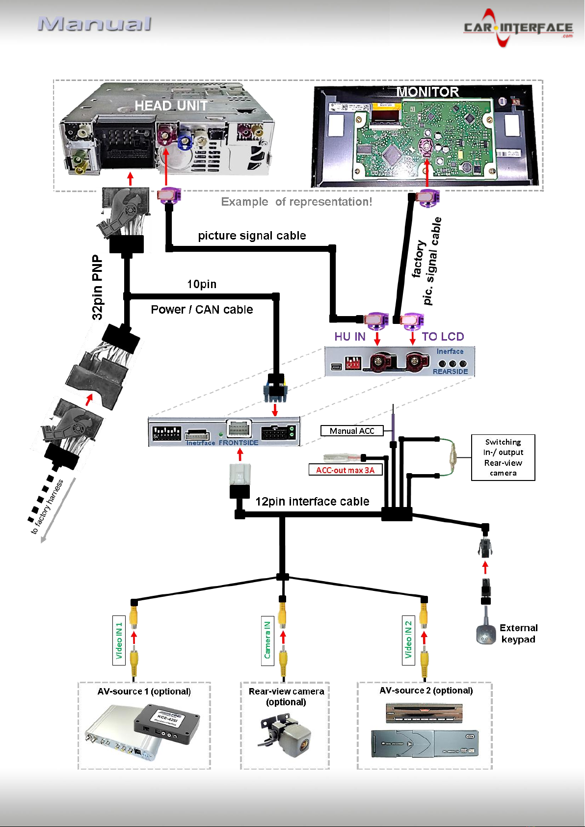
2.2. Connection schema

Version 11.09.2019 HW:CAM (V98) / (V20) CI-RL3-C3D
Page9
2.3. Connections to factory head-unit and monitor
Remove the factory head unit and monitor
2.3.1. Connection to the picture signal cable
Disconnect the factory picture signal cable’s purple coloured female HSD+2 connector at the
rear-side of the head unit and connect it to the purple coloured HSD+2 connector
„TO LCD“ of the video interface .
Connect the not-angled purple coloured female HSD+2 connector of the enclosed picture
signal cable to the previously become free purple coloured male HSD+2 connector of the
video interface.
Connect the angled female purple coloured HSD+2 connector opposite the picture signal
cable to the purple coloured male HSD+2 connector „HU IN“of the video interface.
Note: The colours of the HSD+2 connectors at monitor and head unit may vary.

Version 11.09.2019 HW:CAM (V98) / (V20) CI-RL3-C3D
Page10
2.3.2. Connection to Quadlock - CAN
Connect the female 10pin connector of the 10pin Power / CAN cable to the 10pin connector
of the video interface.
Remove the female 40pin Quadlock connector of the vehicle harness from the rear-side of
the head-unit and connect it to the male 40pin Quadlock connector of the Power / CAN
cable.
Connect the opposite female Quadlock connector of the Power / CAN cable to the previously
become free male Quadlock connector at the rear-side of the head unit.
Table of contents
Other r.LiNK Automobile Accessories manuals


