PS Audio PerfectWave DAC Mk II Manual

Thank you for purchasing the PerfectWave DAC Mk II upgrade kit. The instructions that follow will assist
you through the modications necessary to upgrade your DAC to the DAC Mk II. If you have any questions
concerning your kit or the instructions please don’t hesitate to call us at PS Audio.
We recommend you rst watch the installation videos and then use this handbook as a guide. The rst video
to watch is how to remove the digital input board. It is located here: http://youtu.be/542U4yTFzJQ This will
walk you through identifying if you have the A or B analog board. From there, watch either the A http://
youtu.be/hBWYzjWxYmY or B http://youtu.be/fX3xCW6YFkA style installation procedure.
PS Audio
PerfectWave DAC Mk II Upgrade Kit

Your Kit Should Include the Following
2, 1A, Slow Blow Gold Fuses
1, DAC Mark II Name Plate
1, 1.5” X 0.75 Nylon Washer
1, DAC Mk II Firmware
Hardware images below shown actual size
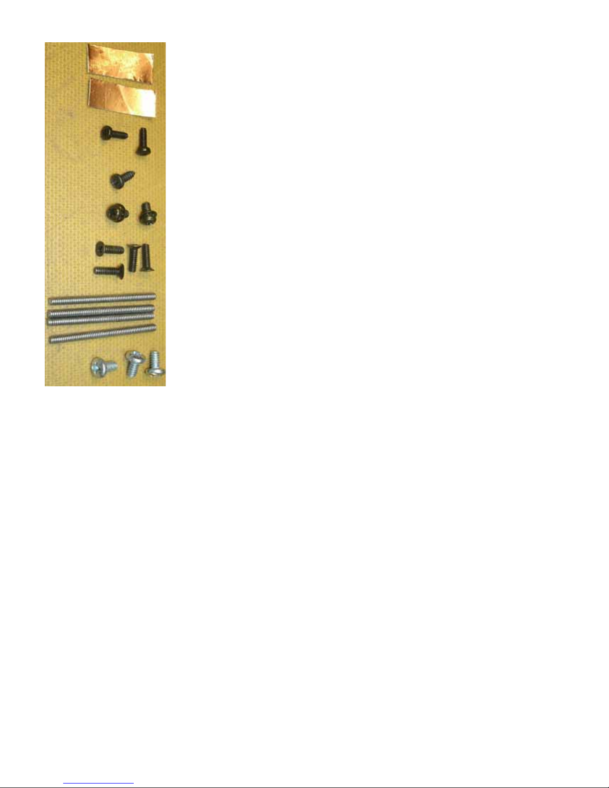
2, Pieces Copper Tape
2, M2.5 Phillips Pan Head Metric Screws
1, 4-24 X 3/8” Tapping Screw
2, M3-0.5 X 6mm Phillips Pan Head Metric Screws
4, 4-40 X 3/8” Phillips Flat Head Screws
4, 4-40 X 11/2” All Thread
3, 6-32 X ¼” Phillips Pan Head Screws

1, White cleaning cloth

1, Upgrade manual
1, DAC II Input Board
1, PerfectWave Remote control II
1, 5/8” wrench
1, Wrist Strap
1, 9/16” wrench
1, 1, ½” open end wrench
1, #1 Phillips screw driver
1, Plastic Tweezers
The Mezzanine Board.

The I2S cables
Type A
Type B

Remove the Top Cover
1. Unplug your DAC from its power source and unplug the AC line cord from the rear panel of the DAC.
2. Find or create a padded work surface such as a table with a piece of carpet or rug.
3. Place your DAC upside down on the white cleaning cloth with the rear panel facing towards you.
4. With the Phillips screw driver, remove the four 4-40 at head screws shown in circles below. No need
to save these screws your kit has new ones.
5. Thread each one of the 4 pieces of all thread into the 4 holes 6 turns each.
Caution: Be sure your work surface is protected as the all thread screws may scratch the surface!
6. Flip the DAC back over right side up on your protected work surface.
7. Uniformly push down on the sides of your DAC. The DAC will drop and the top will pop up as shown to
the right.
8. Reach under the top cover and lift it out of the chassis, ip it over to the left and set it down on the left
side of the DAC as shown in the photo below.

9. Unscrew the 4 pieces of all thread from the top cover bracket and set aside.
10. Wiggle and pull the top cover ground wire from the grounding block.
Note: Some DACs have this ground wire and some do not.
11. Retrieve any pieces of gasket material that may have come o the top cover and fallen into the unit.
There should be 9 pieces of gasket material on the top panel in the locations shown below. Replace
the loose pieces by pressing them back over the bracket where they came from.Note placement of
existing gasket.
12. Move the top cover on the soft cleaning cloth aside to gain work space as needed.
Removing the Old Digital Input Board
13. CAUTION, anti-static precautions are necessary when handling your new DAC Mk II board. Remove the
wrist strap from the plastic bag, open up the loop and put it around your wrist and make it snug.
14. Attach the alligator to the center terminal (ground) of the AC inlet module as shown lower right.
15. Remove the 5 screws that secure the XLR, optical, and HDMI connectors to the rear panel (circles). No
need to save these screws your kit has new ones.
16. Place the 1.5” X 0.755 nylon washer over the outside of the nut on the RCA connector to prevent the
rear panel from being scratched and use the ½” open end wrench to remove the nut from the RCA
connector.
9 Pieces of
Gasket Material
Top Cover
Ground Wire

17. Using your thumb and index nger, carefully rock the J10 ribbon cable back and forth out of the
header as shown right.
18. Using the same method, unplug ribbon cable J11.
19. Unplug the ribbon cable from J13 of the old input board and J3 of the analog board below. The J13
cable will not be reused.
20. Remove the three 6-32 screws (squares) that hold the old board to the 3 spacers.
21. Lift the board out of the chassis moving it away from the rear panel. The piece of copper tape on the
USB connector will peel o of the rear panel, this is ok.
22. Identifying Type A or Type B analog board
There are two types of analog boards. The analog board is the larger bottom board. How the Mark
II Digital Processor board connects to the analog board depends on whether it is an A or a B style of
analog board. The next step is to identify if you have either an A or a B style analog board. Once you
have identied the style, proceed to the A or B installation section to nish the installation.
23. Type A Analog output board. You’ll note that the Type A analog board has a small black
twelve pin socket (J3 page10) adjacent to the two large power supply capacitors.
24. If your Analog DAC board has this socket you will use the short (3 inch/7.5cm) I2S cable.
Use ½” open end wrench
Unplug J11 Remove J13
Copper Tape Unplug J10

25.
26. The I2S cable is labeled with four acronyms.
27. 1.MCK (Blue) 2.BCK (Yellow)3.DAT (Red) 4.LRCK (White).
28. These acronyms will correspond to the colour code on the new MKll digital board I2S input coaxial
sockets.
Type B Analog output board.
29. You’ll note that the type B board has a 16 pin socket on the right hand side (looking from the rear of
the unit) between the metal support posts labeled J2 .
30. If your Analog DAC board has this socket you will use the long (6 inch/15cm) I2S cable.
Other manuals for PerfectWave DAC Mk II
1
Table of contents
Other PS Audio Accessories manuals


