Precia Molen R4 LPW User manual

WWW.PRECIAMOLEN.COMWWW.PRECIAMOLEN.COM
Installation manual
05-21-02-1 MI B / 03/2016
R4 LPW platform scale
Lift versions


05-21-02-1 MI 1
Contents
1. Introduction .......................................................................................................................................... 3
Safety recommendations ........................................................................................................................... 3
Introduction of the various models ............................................................................................................. 3
Required tools and accessories ................................................................................................................. 4
Special installation conditions .................................................................................................................... 4
2. Installation ............................................................................................................................................ 5
Introduction ................................................................................................................................................ 5
Setting up the platform scale ..................................................................................................................... 5
Platform scale alone ............................................................................................................................. 5
Connecting the connection cable to the indicator ...................................................................................... 6
Glands ................................................................................................................................................... 6
Access to connection box ..................................................................................................................... 7
Cabling .................................................................................................................................................. 8
Remounting ........................................................................................................................................... 8
Ramp .................................................................................................................................................... 9
3. Lifting the scale and putting it back to horizontal ................................................................ 10
Lifting ......................................................................................................................................................... 10
Putting the scale back to horizontal ........................................................................................................... 10
4. Cleaning and maintenance ............................................................................................................ 11
General recommendations ......................................................................................................................... 11
Daily cleaning ............................................................................................................................................. 11
Weekly cleaning ......................................................................................................................................... 11
Maintenance .............................................................................................................................................. 12

R4 LPW platform scale - Lift versions
205-21-02-1 MI
05-21-02-1 MI 3
Introduction 1
Safety recommendations
The R4 LPW lift platform scale has moving parts that can represent a potential hazard when
handling them. The safety recommendations presented below must be strictly observed.
•
Do not stay under the platform scale when it is lifted.
•
Handle the platform scale only using front handles. Do not put your fingers into the interstices.
•
Make sure that no object is put onto the platform scale.
•
Forbid all access to any other person than the operator on and near the platform scale during lifting
operations.
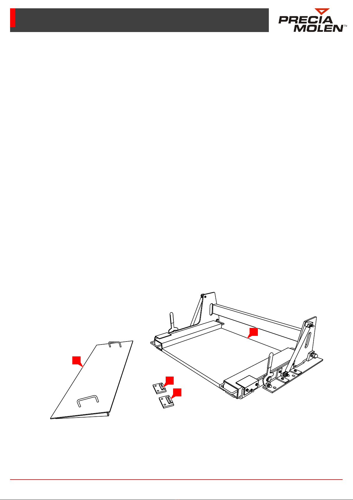
Introduction of the various models
This manual introduces the various installation possibilities for all R4 LWP lift platform scale models. The
models are:
•
800 x 800 mm,
•
1 000 x 800 mm,
•
1 250 x 1 000 mm,
•
1 500 x 1 500 mm.
The R4 LWP lift platform scale is delivered mounted and in closed position (
1
).
In the case of the access ramp option, the platform scale comes with:
•
2plates(
2
),
•
one access ramp (
3
).
1
2
3
2

R4 LPW platform scale - Lift versions
405-21-02-1 MI
Required tools and accessories
Setting up the platform scale implies using an elevation means and the slings corresponding to a maximum
load of:
The installation only requires standard electromechanics tooling.
The required fastening for in-ground fixing is not supplied. It is recommended to use "SPIT" type dowels with
screws and washers:
•
6 M16 x 120 parts for the platform scale (holes Ø 20)
•
4 M8 parts for the access ramp as option (holes Ø 12).
For the implementation procedure, please see the used dowel manual.
Caution with all handling operations. Strictly observe the elementary safety rules that relate to
the used elevation means.
Special installation conditions
The R4 LPW lift platform scale must be installed on a perfectly flat surface. The adjustment of
horizontality must be done in factory.
Models Maximum load Models Maximum load
800 x 800 mm 113 kg 1 250 x 1 000 mm 203 kg
1 000 x 800 mm 133 kg 1 500 x 1 500 mm 296 kg

05-21-02-1 MI 5
Installation 2
Introduction
The receptor and/or ramps can be handled using the handling device and adapted slings or by several people.
The front handles (
1
) and the rear openings (
2
) are used as lifting points.
Caution with injury hazards when handling the platform scale and/or access ramps.
Setting up the platform scale
Platform scale alone
•
Setting the platform scale on the ground at the wished location. As much as possible, plan to have sufficient
space around the receptor so as to ease cleaning operations.
•
On each side of the platform scale, drill the 3 holes* to fix the whole set in the ground through the orifices
specially designed for this (
3
) on the lift plates (
4
).
•
Fasten the 6 screw/washer fixing sets.
•
Unscrew the 2 screw/washer sets (
5
) of each of the 4 transport brackets (
6
) and withdraw the brackets.
* Fastenings not supplied. SPIT dowels with M16 x 120 screws and washers recommended.
3
1
3
1
2
4
5
6

R4 LPW platform scale - Lift versions
605-21-02-1 MI
Connecting the connection cable to the indicator
Glands
To pass the measurement cable through the gland, the procedure is as follows.
•
Unfasten the gland (
1
) and remove it from the flange (
2
). Retrieve the waterproof sealing (
3
) and the ring (
4
).
•
Pass the cable successively through the gland (
1
), the joint (
3
), the ring (
4
) and the flange (
2
).
•
Remount the whole set and moderately fasten the gland so as to let the cable free. The final fastening will
have to be done when the cabling procedure is totally finished.
24
3
1

05-21-02-1 MI 7
Access to connection box
•
Lift the platform scale (See Lifting, page 11)
•
Unscrew the 8 fixing screws (
1
) of the lateral protection sheet (
2
) on the deck notch side (
3
). Be cautious with
the waterproof seal (
4
).
•
Unfasten the 6 fixing screws of the connection box (
5
) and remove the cover (
6
). Be cautious with the
waterproof seal (
7
).
Be cautious with the waterproof seal.
•
Pass the cable through the gland (
8
) located on the wall (
9
) between the connection box (
10
) and the load
cell (
11
)., then through the gland (
12
) located on the connection box.
9
810
4
6
2
5
7
3
1

R4 LPW platform scale - Lift versions
805-21-02-1 MI
Cabling
Proceed to the cabling* of the indicator cable respecting the pin-out indicated on the label stuck on the box
cover.
Remounting
•
Remount the cover on the connection box.
•
Fasten all the glands of the connection box to the indicator definitely.
•
Remount the lateral protection sheet under the platform scale.
•
Proceed to the putting back to horizontal of the platform scale (See "Putting back to horizontal", page 11).
* It is possible to take apart and remove the connection electronics board to ease cabling.
Grounding braid ....... Shielding
Blue .......................... Return (R )
White ........................ Power (V )
Purple ....................... Signal ()
Brown ....................... Signal ()
Green ....................... Power (V )
Yellow........................ Return (R )
Table of contents


