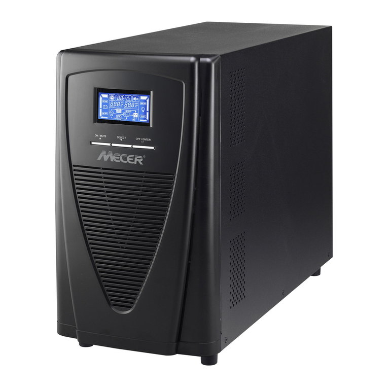
Powertronix Quasar User manual


Manual Registration
Prelim Page i3x3 UPS Preliminary Pages
Issue 2 - November 2001
Manual Registration
STHIS MANUAL IS A CONTROLLED DOCUMENT AND WILL BE PERIODICALL UPĆ
DATED.
SIN ORDER TO ENSURE THAT OU RECEIVE AN AMMENDMENT PLEASE REGĆ
ISTER THIS MANUAL WITH THE TECHNICAL SUPPORT DEPARTMENT B REĆ
TURNING A COP OF THIS FORM TO:
Manual Registration
Number
Name of Registered Holder
Address of
Holder Company
Name/Building
Street/Road
Area/region
Town/City
County/State
Post/Zip Code
Country
Telephone Number
FAX Number
E Mail Address

Amendment Record
Amendment Record
Service Manual
Manual Serial
Number:
Please enter the Manual Serial Nº
for future record
Issue
Nº
Issue
Date Amendment Amended By Date
1Initial issue ć ć

Service Manual
Amendment Record
Prelim Page iii 3x3 UPS Preliminary Pages
This Ser ice manual contains information concerning the installation operation and ser ice of the folĆ
lowing UPS
EQUIPMENT PART NUMBER
With battery Without battery
10 kVA UPS
15 kVA UPS
20 kVA UPS
30 kVA UPS

UTILITY
SUPPLY
WARNING
PLEASE
NOTE
Service Manual
Limitations of Use
Prelim Page iv 3x3 UPS Preliminary Pages
Issue 2 - November 2001
Limitations of Use
ELECTROMAGNETIC COMPATABILITY
The equi ment covered by this manual com lies with the requirements of the EMC DirecĆ
tive 89/336/EEC and the ublished technical standards. Continued com liance requires
installation in accordance with these instructions and use of manufacturer a roved accesĆ
sories only.
WARNINGThe UPS is a Class A roduct.
When used in a domestic environment a unit may cause radio interference,
If this is the case the user may be required to take additional measures
WARNING HIGH EARTH LEAKAGE CURRENT.
Earth connection is essential before connecting the utility su ly.
This equi ment must be earthed in accordance with local electrical codes.
WARNING This UPS does not incor orate automatic backĆfeed rotection. A warning label must be
fitted to all external rimary ower isolators stating:
ISOLATE THE UNINTERRUPTIBLE POWER SYSTEM BEFORE WORKING ON THIS CIRCUIT.
The UPS should not be su lied from electrical ower systems of the `IT'
(Im édance à Terre) ty e.
(IEC 364 Ć ELECTRICAL INSTALLATION OF BUILDINGS)
Note: Where use on `IT' systems is required an o tional in ut isolation transformer should
be fitted.
CAUTION This equi ment is fitted with RFI su ression filters
Earth leakage exceeds 3.5mA but is less than 300mA.
Transient and steadyĆstate earth leakage currents, which occur when starting the equi Ć
ment, should be taken into account when selecting instantaneous RCCB or RCCD devices.
Note also that the earth leakage currents of the load will be carried by this RCCB or RCCD.
These roducts are intended for Commercial/Industrial use only, and are not suitable for
use in any life su ort a lications.

Service Manual
Important Instructions for safe use
Prelim Page v 3x3 UPS Preliminary Pages
Important Instructions for safe use
GENERALThe UPS must be a roved engineer before it is ut into serĆ
vice. Failure to observe this condition will invalidate any im lied warranty.
In common with other ty es of high ower equi ment, dangerous voltages are resent with
the UPS and battery enclosure. The risk of contact with these voltages is minimised as the
live com onent arts are housed behind a hinged lockable door.
Further internal safety screens make the equi ment rotected to IP20 standards.
No risk exists to any ersonnel when o erating the equi ment in the normal manner, followĆ
ing the recommended o erating rocedures.
All equi ment maintenance and servicing rocedures involving internal access, should be
carried out by trained ersonnel.
The UPS is for indoor use only. It must be rotected from rain or excessive moisture and
installed in a clean environment, free from flammable liquids, gasses, or corrosive subĆ
stances. Do not ut drinks, lants, or any other containers holding liquids, on to of the unit.
BATTERIES Battery manufacturers su ly details of the necessary recautions to be observed when
working on, or in the vicinity of, a large bank of battery cells. These recautions should be
followed at all times.
Particular attention should be aid to the recommendations concerning local environĆ
mental conditions and the rovision of rotective clothing, first aid and fireĆfighting facilities.
TEST EQUIPMENT
When the battery is under charge it is earthĆreferenced about its midĆ oint e.g. if the battery
is being charged at 460V the battery extremities will be =230V and Ć230V with res ect to
neutral (earth). When using mains owered test equi ment such as oscillosco es in the
UPS high voltage area, always use a differential mode of o eration to avoid the need to disĆ
connect the oscillosco e frame earth.
PERSONNEL
When working inside the UPS (trained ersonnel only) is recommended that rotection be
worn to revent eye damage, should an electric arc be struck by mishandling or severe
electrical fault.
Some of the ower com onents are very heavy. If their removal is necessary ensure that
sufficient man ower is available, otherwise use adequate mechanical handling equi ment.
When working in the general area of the UPS where high voltages are resent, a second
erson should be standingĆby to assist and summon hel in case of accident.

Service Manual
Personnel Categorisation
Prelim Page vi3x3 UPS Preliminary Pages
Issue 2 - November 2001
Personnel Categorisation
The following definitions re given to c tegorise the scope, nd use of this service
m nu l:
Oper tor/User
This service manual is outside the sco e for use by ersonnel who have received instrucĆ
tion on the correct o eration of the UPS controls; limited to o eration of the unit circuit
breakers and the Front Control Panel; o erator/users are not ermitted to remove any anĆ
els which are retained by screws.
Competent Personnel
The Troubleshooting section, and Service rocedures contained in this manual are norĆ
mally outside the sco e of ersonnel categorised com etent; though they may be aware
of the dangers a ro riate to working with hazardous voltages. A Com etent engineer is
deemed to have sufficient technical skills/training to make electrical connections, install
batteries, close and o en circuit breakers/fuses etc. (i.e. a qualified electrician) he is not
categorised as service ersonnel.
Service Personnel
This
etraining and are assword authorised.
Service manual is designed for use by engineers who have received the relevant
Import nt Symbols
The warning triangle shown above indicate ersonal safety instructions.
Follow these instructions carefully to avoid injury.

Service Manual
Specification
Prelim Page vii UPS Preliminary Pages
Issue 2 - November 2001
Specification
10kVA 15kVA 20kVA 30kVA
Input Data
Nominal Input Voltage 400V 3 phase, neutral and earth
Input Voltage Range 300 ć 480Vac (330 ć 480Vac full charging capability)
Nominal Input Frequency 50/60Hz
Input Frequency Range 40 ć 70Hz
Maximum Input Current at Nominal Input Voltage 18.5A 25.3A 31.7A 45.0A
Input Current Harmonic Distortion (THD) <30% (without filter)
Input Power Factor 0.95 (over specified load and voltage ranges)
Output Data
Nominal Output Voltage 380, 400 or 415Vac selectable
Output Voltage Adjustment Range 360 ć 415Vac
Output Voltage Stability
Static Balanced Load
Static 50% Unbalanced Load
Static 100% Unbalanced Load
Dynamic 50% Load Step
Dynamic 100% Load Step
±1%
±3%
±5%
±3%
±5%
Output Voltage Transient Recovery Time <30ms (to 3% RMS)
Output Voltage Distortion (THD)
Linear Load
Non Linear Load (100% 3:1 Crest Factor Load)
<3%
<5%
Output Voltage Phase Displacement
Balanced Load
100% Unbalanced Load
120° ±1%
120° ±3%
Nominal Output Frequency 50 or 60Hz
Output Frequency Regulation
Synchronised With Input
Free Running
±1% or ±4%, selectable
±0.005%
Maximum Slew Rate 1Hz/sec
Nominal Output Power Rating
kVA
kW
10
8
15
12
20
16
30
24
Output Nominal Power Factor 0.8
Overload Capability on Inverter (Load Will Transfer to
Static Bypass if Times are Exceeded) 125% for 10 minutes, 150% for 10 seconds
Output Short Circuit Current 300% of nominal current for 100ms
Maximum Load Crest Factor 3:1 (at full load without deĆrating)

Service Manual
Specification
Prelim Page viiiUPS Preliminary Pages
Issue 2 - November 2001
10kVA 15kVA 20kVA 30kVA
Intermediate DC Circuit Data
Internal Battery Type valve regulated, sealed, lead acid cells
Number of Battery Cells 192
Nominal Battery Voltage 384Vdc
Internal Battery Rating 7.2Ahr 2 x 7.2Ahr 2 x 7.2Ahr 3 x 7.2Ahr
Full Load Autonomy Time With Standard Internal Battery
(For part load and battery configuration Autonomy times
refer to the table on page Ćxiii)
6 minutes 9 minutes 6 minutes 6 minutes
DC Bus Overvoltage Trip 500Vdc
End of Battery Discharge Voltage 320Vdc
Battery PreĆalarm Discharge Voltage Level 350Vdc
Battery Charger Nominal Float Voltage at 20°C 432Vdc
Battery Charger Voltage Stability ±1%
Battery Charger Output Voltage Ripple <1%
Maximum Battery Recharging Current 1, 3, 5 or 7A (Selectable)
Automatic Battery Test 12, 24 or 48 hour impedance test
System Data
Topology True OnĆline double conversion, high frequency,
transformerless design
Power Upgrade es ć up to a maximum rating of 30kVA
StartĆup On Battery es
System Efficiency (Excluding Battery Charging)
50% Linear Load
100% Linear Load
88%
90%
88%
90%
89%
91%
90%
91%
Full Load Inverter Efficiency 94% 94% 94% 94%
Operating Temperature Range 0° Ć 40°C (20°C for optimal battery lifetime)
Storage Temperature Range Ć20° to 70°C (excluding battery)
Operating Relative Humidity Range <95% (nonĆcondensing)
Maximum Altitude Above Sea Level 1000m before deĆrating
Audible Noise Level At 1 Metre <52dBA
Relay Communications Card
Alarm Contacts
DB9 connector
On Battery
Low Battery
Internal Terminals
On Battery
Low Battery
On Bypass
UPS On
Remote Stop Contacts Open to disable inverter and static bypass
Cable Entry Bottom entry at rear of unit
This manual suits for next models
4
Table of contents
Other Powertronix UPS manuals