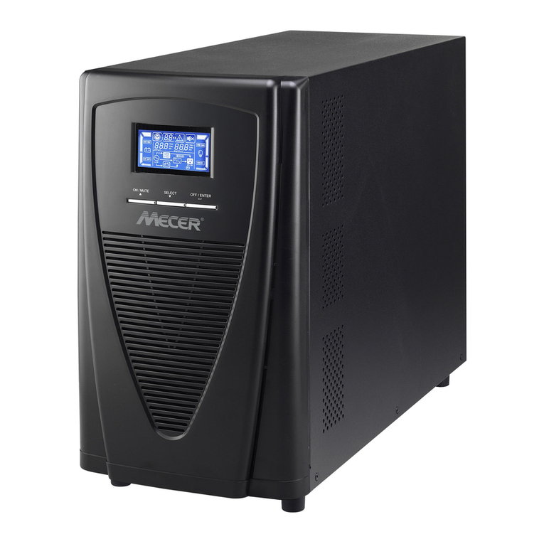
Powertronix Mizar-Alcor User manual

R&D
–
SERVICE MANUAL DT0489-E00
Powertronix spa reserves the right to modify this document without notice
POWERTRONIX
Mizar-Alcor
Service Manual
Document : DT0489 English PTX
Revision Date Checked Approved
00 07-09-2009 07-09-2009
Ghezzi R. 07-09-2009
Ghezzi R.

R&D
–
SERVICE MANUAL DT0488
Powertronix spa reserves the right to modify this document without notice
Page. 2 of 72
Index
1. GENERAL ITEMS......................................................................................................4
1.1 INTRODUCTION...................................................................................................4
1.1.1 GENERAL FAULT IDENTIFICATION PROCEDURE...................................4
1.2 TOOLS..................................................................................................................5
1.2.1 PORTABLE PC WITH SOFTWARE.............................................................5
1.2.2 OSCILLOSCOPE .........................................................................................5
1.2.3 DIGITAL MULTIMETER (DSM)....................................................................5
1.2.4 DISCHARGING RESISTOR.........................................................................5
2UPS COMPONENTS RECOGNIZING .......................................................................6
2.1 UPS CLOSED.......................................................................................................6
2.2 INNER VIEW WITH SAFETY COVER REMOVED...............................................7
2.3 REAR UPS DESCRIPTION..................................................................................8
2.4 UPS-10-15KVA ELECTRONIC PARTS LAYOUT.................................................9
2.5 UPS-20-30KVA ELECTRONIC PARTS LAYOUT...............................................10
2.6 UPS-10-15KVA BOARDS..................................................................................11
2.7 UPS-20-30KVA BOARDS..................................................................................11
2.8 BOARDS LAYOUT..............................................................................................12
2.8.1 UPS-10-15KVA POWER INTERFACE BOARD COMPONENT LAYOUT..12
2.8.2 UPS-20-30KVA POWER INTERFACE BOARD COMPONENT LAYOUT..13
2.8.3 CS0150 UPS-10-15KVA UPS-20-30KVA CONTROL BOARD...................14
2.8.4 CS0153 UPS-10-15KVA UPS-20-30KVA POWER SUPPLY BOARD........15
2.8.5 CS0098 RELAY & COMUNICATION BOARD............................................16
2.8.6 SNMP COMUNICATION BOARD...............................................................16
2.8.7 TERMINAL BLOCKS..................................................................................17
3TROUBLESHOOTING.............................................................................................18
3.1 POWER FUSE....................................................................................................18
3.1.1 UPS-10-15KVA...........................................................................................18
3.1.2 UPS-20-30KVA...........................................................................................19
3.2 CHECK ALL PFC & INVERTER OUT IGBTS. ....................................................20
3.2.1 UPS-10-15KVA...........................................................................................20
3.2.2 UPS-20-30KVA...........................................................................................21
3.2.3 CHECK AUXILIARY POWER SUPPLY CONTROL BOARD......................23
3.2.4 LED STATUS .............................................................................................25
3.2.5 CHECK CONTROL BOARD.......................................................................26
3.2.6 CHECK POWER SUPPLY VOLTAGE........................................................26
3.3 POWER INTERFACE UPS-10-15KVA BOARD..................................................27
3.4 POWER INTERFACE UPS-20-30KVA BOARDS (CS0151)...............................29
4PC BASED CHECKS AND SETTINGS ...................................................................31
5ELECTRICAL DIAGRAM.........................................................................................40
5.1 PCB ELECTRICAL DIAGRAM INDEX................................................................40
5.1.1 DE1237 UPS 10-15KVA GENERAL DIAGRAM .........................................41
5.1.2 DE1112 UPS 20-30KVA GENERAL DIAGRAM .........................................43
5.1.3 DE0098 RELAY & COMMUNICATION BOARD.........................................46
5.1.4 DE0138 TEMPERATURE SENSOR PCB..................................................47

R&D
–
SERVICE MANUAL DT0488
Powertronix spa reserves the right to modify this document without notice
Page. 3 of 72
5.1.5 DE0143 BATTERY FUSE PCB (BATTERY 7.2-9AH) / DE0157 BATTERY
FUSE PCB (BATTERY 4.5-5.2AH)...........................................................47
5.1.6 DE0150 CONTROL LOGIC........................................................................48
5.1.7 DE0151 UPS 20-30KVA INVERTER DRIVER & FEEDBACK....................59
5.1.8 DE0152 UPS 10-15KVA INVERTER DRIVER & FEEDBACK....................65
5.1.9 DE0153 POWER SUPPLY BOARD ...........................................................69
5.1.10 DE0111 UPS 10-30KVA H-F FILTER.........................................................70
5.1.11 DE0155 LCD MIMIC DISPLAY...................................................................71
5.1.12 DE1235 BATTERY STRING.......................................................................72

R&D
–
SERVICE MANUAL DT0488
Powertronix spa reserves the right to modify this document without notice
Page. 4 of 72
WARNING !
The following documentation requires the knowledge and the support of
USER MANUAL .
1. GENERAL ITEMS
1.1 INTRODUCTION
The UPS contains complex electronic control circuits which require a firm understanding
in order to carry out comprehensive fault diagnosis and repair of the equipment.
The aim of the information contained in this chapter is to provide sufficient guidance to
the trained service engineer, to enable successful fault location to printed circuit board
level. When a faulty circuit board or component has been identified, it should be replaced
or returned to the nearest service centre to repair.
The troubleshooting information include the following items :
•Component location and identification
•Diagnostic information
•Troubleshooting procedures
•Test procedures
Note: when following the procedures cross referencing is inevitable, therefore
it is recommended that this chapter is read in its’ entirety, before commencing
work on the equipment.
There is no practical way detecting an impending UPS malfunction, as most problems do
not emerge as a gradual performance degradation. Generally the UPS will either work
correctly or shut down with or without a warning indication.
In the event of a UPS malfunction troubleshooting should be carried out methodically
along the following guide lines.
1.1.1 General Fault Identification Procedure
When first summoned to the UPS fault the immediate action should be to observe and
record the LED indication displayed on the unit operator panel.
a) Determine the UPS power status.
b) Note the control switch configuration, and also the warning horn sequence if it is
operating.
WARNING: during the troubleshooting it will be necessary to power up the
unit whit the side or top covers removed. In this situation exposure
to potentially lethal voltage is possible even whit the input utility
supply switched off.
Take great care at all switch to minimise the risk of contact whit live
voltage, especially when working around the battery or DC bus

R&D
–
SERVICE MANUAL DT0488
Powertronix spa reserves the right to modify this document without notice
Page. 5 of 72
c) Power down the unit, and ensure that the DC Bus Safety discharge check is
carried out.
d) Gain access to the internal components follow the procedure for removing the UPS
covers.
e) Check the status of the UPS fuses refer to the check list on table 1,2,3
f) Apply power and analyse LCD indications
g) Refer troubleshooting chart to identify possible fault
h) Check PFC converter power components. Pag.20 for component location
i) Check inverter power components. Pag.20 for component location
1.2 TOOLS
Special mechanical tools aren’t required to service the UPS, a normal electricians tool kit
will be adequate. Are necessary insulating gloves and glasses for safety. However to
carry out the check procedures in this chapter the following test equipment will be
required.
1.2.1 Portable PC with software
UPS Maintenance UCT
See the chapter 4
is absolutely necessary for a skilled service engineer because every set point or UPS
logic status or regulation constant can be set or checked only via PC and software
1.2.2 Oscilloscope
A dual trace oscilloscope, which has the ability to sum the two channel, allowing
differential voltage measurements to be made.
For the measure points that it is needed to check it is mandatory to have the
oscilloscope insulated from the supply whit a transformer or battery fed scope.
A storage facility is useful, but not essential.
1.2.3 Digital multimeter (DSM)
A standard digital multimeter is necessary to take essential measurements ; a reference
type could be the FLUKE 70 series multimeter or equivalent.
1.2.4 Discharging resistor
To discharge electrolytic capacitors bank in a short time it’s necessary use a discharging
resistor , ref. value 10K / 50W nom. Before using discharging resistor verify that
battery circuit breaker is open !

R&D
–
SERVICE MANUAL DT0488
Powertronix spa reserves the right to modify this document without notice
Page. 6 of 72
2 UPS COMPONENTS RECOGNIZING
To do servicing it’s necessary to recognize UPS parts , so , before troubleshooting ,
some pictures of UPS and parts will be shown in the following pages . To check pictures
it’s necessary to follow the UPS general schematic diagram (DE1244 and DE1245 )
attached at the end of this document .
2.1 UPS CLOSED
Fig.1
*** WARNING !! Before removing safety covers after power disconnection , it’s
necessary to wait for 10 minutes to have discharged inner capacitors . In any case be
careful and never touch circuits or components before a voltage check
UPS Control Panel
UPS Side Cover panel
UPS Front Cover
BATTERY Front Cover
E:P:O: Command

R&D
–
SERVICE MANUAL DT0488
Powertronix spa reserves the right to modify this document without notice
Page. 7 of 72
2.2 INNER VIEW WITH SAFETY COVER REMOVED
Fig.2
UPS Power Section
UPS Battery Location
BATTERY Connections
BATTERY String

R&D
–
SERVICE MANUAL DT0488
Powertronix spa reserves the right to modify this document without notice
Page. 8 of 72
2.3 REAR UPS DESCRIPTION
Fig.3
Breaker
SNMP-Net Com
Slot location
RS232 & Status
Remote Control
Slot location
Output
Air window
Tagblock

R&D
–
SERVICE MANUAL DT0488
Powertronix spa reserves the right to modify this document without notice
Page. 9 of 72
2.4 UPS-10-15KVA ELECTRONIC PARTS LAYOUT
LEFT SIDE
Fig.4
RIGHT SIDE
Fig. 5
NEUTRAL BAR
Connection
DC Busbar
HEATSINK
FAN
Power Impedence
DC
Busbar
Power Impedence
CS0150
CS0153

R&D
–
SERVICE MANUAL DT0488
Powertronix spa reserves the right to modify this document without notice
Page. 10 of 72
2.5 UPS-20-30KVA ELECTRONIC PARTS LAYOUT
LEFT SIDE
Fig. 6
RIGHT SIDE
Fig. 7
NEUTRAL BAR
CONNECTION
DC Busbar
HEATSINK
Power Impedence
DC Busbar
Power Impendence
Fuse
Fuse
CS0153
CS0150
Table of contents
Other Powertronix UPS manuals