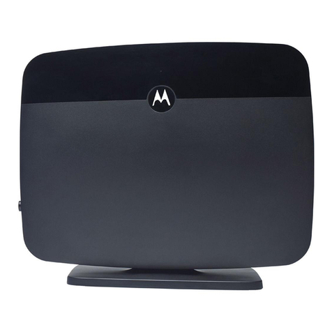
Planex BLW-54SAG User manual

2.4/5.0 GHz IEEE 802.11 Super a+g
108Mbps Wireless LAN Router
BLW-54SAG

Contents
Chapter 1. Introduction ..................................................................................................4
1.1 Overview of the BLW-54SAG ................................................................................. 4
1.2 BLW-54SAG Applications....................................................................................... 4
1.3 Package Contents ................................................................................................... 5
1.4 The Back Panel ....................................................................................................... 6
1.5 The Front Panel ...................................................................................................... 7
1.6 System Requirements............................................................................................. 8
Chapter 2. Connecting the BLW-54SAG ........................................................................9
Chapter 3. Configuring the BLW-54SAG .....................................................................11
3.1 How to Access the Web-based Utility ...................................................................11
3.2 The Setup Tab - Basic Setup .................................................................................11
3.3 The Setup Tab - DDNS......................................................................................... 18
3.4 The Setup Tab - MAC Address Clone .................................................................. 19
3.5 The Setup Tab – Advanced Routing .................................................................... 20
3.6 The Wireless Tab - Basic Wireless Settings ........................................................ 22
3.7 The Wireless Tab - Wireless Security.................................................................. 24
3.8 The Wireless Tab - Wireless MAC Filter............................................................. 27
3.9 The Wireless Tab - Advanced Wireless Settings................................................. 28
3.10 The Security Tab - Firewall ................................................................................. 33
3.11 The Security Tab - VPN Passthrough ................................................................. 34
3.12 The Access Restrictions Tab - Internet Access Policy......................................... 35
3.13 The Applications and Gaming Tab - Port Range Forwarding............................ 39
3.14 The Applications & Gaming Tab - Port Range Triggering ................................. 41
3.15 The Applications and Gaming Tab - DMZ........................................................... 43
3.16 The Applications and Gaming Tab - QoS ............................................................ 43
3.17 The Administration Tab - Management.............................................................. 47
3.18 The Administration Tab - Log.............................................................................. 50
3.19 The Administration Tab - Diagnostics................................................................. 51
3.20 The Administration Tab - Factory Defaults........................................................ 52
3.21 The Administration Tab - Firmware Upgrade.................................................... 52
3.22 The Administration Tab - Restart........................................................................ 53
3.23 The Status Tab - Router ....................................................................................... 54
3.24 The Status Tab - Local Network .......................................................................... 55
3.25 The Status Tab - Wireless .................................................................................... 57
2

Chapter 4. Upgrading Firmware ..................................................................................59
Chapter 5. Specifications ..............................................................................................60
Chapter 6. Safety Statement ........................................................................................61
3

Chapter 1. Introduction
1.1 Overview of the BLW-54SAG
The BLW-54SAG is a small desktop router that sits between your local Ethernet
network and a re-mote network (e.g., the Internet). The BLW-54SAG contains a WAN
port connecting to an external ADSL/Cable modem, a four-port 10/100Mbps Ethernet
switch for connection to PCs on your local wired network, and one wireless interfaces for
connection to your local wireless 802.11a/b/g network supporting a data rate of up to 108
Mbps. Data comes into the BLW-54SAG from the local wired and wireless LAN and
then is “routed” to the Internet, and vice versa.
1.2 BLW-54SAG Applications
1.2.1 Accessing the Internet
The most common use of the BLW-54SAG is to provide shared Internet access to allow
everyone on your LAN to surf the web and send/receive emails or files. The BLW-54SAG
can automatically ac-quire a public IP address when connecting to the Internet. In turn,
it will automatically assign IP ad-dresses to PCs (requesting DHCP client devices) on
your LAN - you don’t have to apply for and assign IP addresses to PCs on your network.
Accessing Servers from the Public Network If you want special servers to be accessible
to remote users across the Internet (e.g., an e-mail server, an FTP server, or a web
server), you can configure the BLW-54SAG to proxy the service using its (public) IP
address. It means a remote user can access the server by using the BLW-54SAG’s IP
address. Upon receiving a request, the BLW-54SAG will re-direct the request to the
actual server on your local network.
1.2.2 Operating as an Access Point
Additionally, the Wireless Router can also be configured as an Access Point, and acts as
the central point of your local wireless network supporting a data rate of up to 108 Mbps.
It allows client devices on your wireless network to access the Internet, to communicate
with other wireless devices on your wireless network, or to communicate with devices on
your wired LAN network. Since 802.11g is based on the same 2.4GHz radio band as the
802.11b technology, the BLW-54SAG can inter-operate with existing 11Mbps 802.11b
devices. Therefore you can protect your existing in-vestment in 802.11b client cards, and
migrate to the high-speed 802.11g standard as your needs grow. Alternatively, you can
4

configure the BLW-54SAG to provide an 802.11a WLAN environment.
1.3 Package Contents
Please verify that the product package contains all of the following parts.
zBLW-54SAG
zQuick Installation Guide
zCD-ROM (User’s Manual)
zAC Adapter
zUTP Cable
zStand
zWarranty Card
Please contact your local dealer or distributor if any of the above items is missing.
5

1.4 The Back Panel
The Router’s ports and Reset button are located on the back panel of the Router.
RESET Button
WAN
LAN 1, 2, 3, 4
POWER
RESET
Button
There are two ways to reset the Router's factory defaults. Either press
the RESET button, for approximately five seconds, or restore the
defaults from the Administration tab - Factory Defaults in the Router's
Web-based Utility.
WAN The Internet port is where you will connect your broadband Internet
connection.
LAN 1, 2, 3, 4 These ports (1, 2, 3, 4) connect the Router to your networked PCs and
other Ethernet network devices.
POWER The POWER port is where you will connect the power adapter.
6

1.5 The Front Panel
The Router’s LEDs, which indicate the status of the Router and network activities, are
located on the front panel.
WAN
LAN 1, 2, 3, 4
WLAN-G
WAN Green. The WAN LED lights up when there is a connection made
through the WAN port.
LAN 1, 2, 3,
4
Green. These numbered LEDs, corresponding with the numbered ports
on the Router’s back panel, serve two purposes. If the LED is
continuously lit, the Router is successfully connected to a device through
that port. A flashing LED indicates network activity over that port.
WLAN-G Green. The WLAN LED flashes when there is a successful Wireless-G
connection.
WLAN-A Green. The WLAN LED flashes when there is a successful Wireless-A
connection.
PPPoE Green. The PPPoE LED indicates when the PPPoE function is being
used. This LED will remain lit as long as PPPoE is enabled.
Power Green. The Power LED lights up and will stay on while the Router is
powered on. When the Router goes through its self-diagnostic mode
during every boot-up, this LED will flash. When the diagnostic is
complete, the LED will be solidly lit.
POWER
PPPoE
WLAN-A
7

1.6 System Requirements
zSupported Platforms
Windows 98/98SE/Me/2000/XP PC equipped with an Ethernet (RJ-45) port
MacOS 8.x/9.x/X computer equipped with an Ethernet (RJ-45) port
zRequired Networking Equipment
A twisted-pair cable x n (n= the number of computers attached to the product)
zAbout Web Configuration Screen
The system configuration of the product is adjusted via a Web browser. Please make
sure that
1) a Web browser has been already installed on your computer and
2) JavaScript is enabled on that browser.
zWindows and Mac OS
Microsoft Internet Explorer 5.0 or greater / NetScape Navigator 6.0 or greater
8

Chapter 2. Connecting the BLW-54SAG
Planex recommends using the Setup Wizard on the Setup CD-ROM for first-time
installation of the Router. For advanced users, you may follow the instructions in this
chapter, and then configure the Router through its Web-based Utility.
DSL/Cable
Modem
UTP
Existing Connection
BLW-54SAG
To PCs
Choose an Installation Site
Select a suitable place on the network to install the BLW-54SAG. Ensure the
BLW-54SAG and the DSL/Cable modem are powered OFF.
Connect LAN Cables
Use standard LAN cables to connect PCs to the Switching Hub ports on the
BLW-54SAG. Both 10BaseT and 100BaseT connections can be used simultaneously.
If required, connect any port to a normal port on another Hub, using a standard LAN
cable. Any LAN port on the BLW-54SAG will automatically function as an Uplink port
when required.
Connect WAN Cable
Connect the DSL or Cable modem to the WAN port on the BLW-54SAG. Use the cable
supplied with your DSL/Cable modem. If no cable was supplied, use a standard cable.
9

Power Up
•Power on the Cable or DSL modem.
•Connect the supplied power adapter to the BLW-54SAG and power up.
Caution:
Use only the power adapter provided. Using a different one may cause hardware damage
Now that the hardware installation is complete, proceed to Chapter3: Configuring the
BLW-54SAG.
10
Other manuals for BLW-54SAG
1
Table of contents
Other Planex Network Router manuals

Planex
Planex BRL-04FXP User manual

Planex
Planex MZK-W04NU User manual

Planex
Planex BLW-04GZ-PK User manual

Planex
Planex CQW-MR200 User manual

Planex
Planex BLW-04G User manual

Planex
Planex BRL-04AX User manual

Planex
Planex MZK-W04N User manual

Planex
Planex MZK-WDPR User manual

Planex
Planex BRL-04EX User manual

Planex
Planex BLW-04EX User manual

Planex
Planex eXgate Series User manual

Planex
Planex FX-16IM User manual

Planex
Planex BRM-04 User manual

Planex
Planex FMG-24K User manual

Planex
Planex BRL-04FM User manual

Planex
Planex BLW-54CW3 User manual

Planex
Planex FX-16NW User manual

Planex
Planex BLW-54SAG User manual

Planex
Planex FMS-24K User manual

Planex
Planex BLW-54SG User manual