PennBarry Zephyr Z1 Installation guide

1401 North Plano Road, Richardson, Texas 75081
Phone: 972-234-3202 Fax: 972-497-0468
Unpacking
Place carton in an upright position and
remove staples or use a sharp (knife
edge) tool to CAREFULLY cut or scribe
the sealing tape on both sides at the top
of the carton. Open carton flaps. Remove
any cardboard and wooden filler pieces,
as well as loose components or acces-
sories shipped with the unit.
Carefully remove the unit from the carton.
Inspect the unit for any damage that may
have occurred during transit and check
for loose, missing or damaged parts.
Installation
WARNING
To reduce the risk of fire, electrical
shock, or injury to persons, observe
the following:
1. Use this unit only in the matter
intended by the manufacturer. If you
have questions, contact the manu-
facturer at the address or telephone
number listed in the warranty.
2. Before servicing or cleaning
unit, switch power off at service
panel and lock service panel
to prevent power from being
switched on accidentally.
3. Installation work and electrical
wiring must be done by a qualified
person(s) in accordance with all
applicable codes and standards,
including fire-rated construction
codes and standards.
4. Sufficient air is needed for proper
combustion and exhausting of gases
through the flue (chimney) of fuel
burning equipment to prevent back-
drafting. Follow the heating equip-
ment manufacturer’s guideline and
safety standards such as those pub-
lished by the National Fire
Protection Association (NFPA), and
the American Society for Heating,
Refrigeration and Air Conditioning
Engineers (ASHRAE), and the local
code authorities.
5. When cutting or drilling into wall
or ceiling, do not damage electrical
wiring and other hidden utilities.
6. Ducted fans must always be
vented to the outdoors.
7. Acceptable for use over a bathtub
or shower when installed in a GFCI
protected branch circuit.
8. Install fan at least five feet
(1.52m) above floor.
9. Never place a switch where it can
be reached from a tub or shower.
10. This unit must be grounded.
Operation & Maintenance Manual
Zephyr Ceiling/Wall Ventilating Fans Model Z1
Printed in the USA Jan 2005
PART #99042570
Receiving and Handling
PennBarry fans are carefully inspected before leaving the factory. When the unit is
received, inspect the carton for any signs of tampering. Inspect the unit for any dam-
age that may have occurred during transit and check for loose, missing or damaged
parts. Mishandled units can void the warranty provisions. PennBarry is not responsible
for damages incurred during shipment.
Avoid severe jarring and/or dropping. Handle units with care to prevent damage to com-
ponents or special finishes.
Storage
Long-term storage requires special attention. Units should be stored on a level,
solid surface, preferably indoors. If outside storage is necessary, protect the
units against moisture and dirt by encasing the cartons in plastic or some similar
weatherproof material.
Figure 3: Wiring Diagram
Figure 1
Figure 2
Black
Black
120 VAC Line In
Switch or Timer
Switch Box
Receptacle
Black to
Black
Ground
White to
White
White to
White
Green to
Green or
Bare Wire
Housing
Flap
Wiring
Cover
Screwdriver
Slot
Read carefully before attempting to assemble, install, operate or maintain the product described. Protect yourself and others by
observing all safety information. Failure to comply with instructions could result in personal injury and/or property damage! Retain
instructions for future reference.
PLEASE READ AND SAVE THESE INSTRUCTIONS.

Operation & Maintenance Manual Zephyr Ceiling/Wall Ventilating Fans Model Z1
2 PENNBARRY 1401 North Plano Road, Richardson, Texas 75081
Phone: 972-234-3202 Fax: 972-497-0468
CAUTION
1. For general ventilating use only.
Do not use to exhaust hazardous
or explosive materials and vapors.
2. To avoid motor bearing damage
and noisy and/or unbalanced
impellers, keep drywall spray, con-
struction dust, etc. off power unit.
3. Please read specification label
on product for further information
and requirements.
INSTALLATION
1. Remove motor plate from housing
by pushing down on rib in plate
while pulling out on side of housing.
Motor plate may also be removed by
inserting a straight-blade screw driv-
er into slot in housing and twisting
screw driver (Figure 1).
2. Remove wiring cover from housing
by pulling straight out. Unit is
shipped ready to wire through the
top of housing. To wire through the
side, bend housing flap to cover top
hole and expose side hole. DO NOT
BREAK OFF FLAP. If flap breaks,
plug unused hole using standard
electrical hole plug (Figure 2).
3. Turn off electrical power at service
entrance and connect power cable
to housing using appropriate con-
nector. Wire black to black, white to
white, green to green or bare wire.
Push all wiring up into corner
of unit and replace wiring cover.
Make sure cover holds housing flap
in place against side or
top of housing.
Do not allow wires
to extend outside of the
wiring box. Wire left exposed will become
pinched or cut when motor
plate is installed. Electrical shock
may result (Figure 3).
4. Choose the location for your
fan. For best performance, use the
shortest possible duct run
and a minimum number of elbows.
For wall installations: position unit so
damper flap closes when unit is off.
5a. New Installation prior to finishing
the ceiling or wall:
Make sure the housing will be flush
with the finished ceiling or wall.
Slotted tabs are provided to locate
housing flush with 1/2" ceiling or wall
material. Bend tabs outward 90º
(Use a screw driver if desired) and
position housing so that tabs rest
against bottom edge of joists (or
front of stud). Nail housing to joist or
stud using four nails to ensure a
solid, quiet installation. Ceiling instal-
lations: Tabs on opposite side of
housing can be bent outward to rest
on top of 1/2" ceiling material and
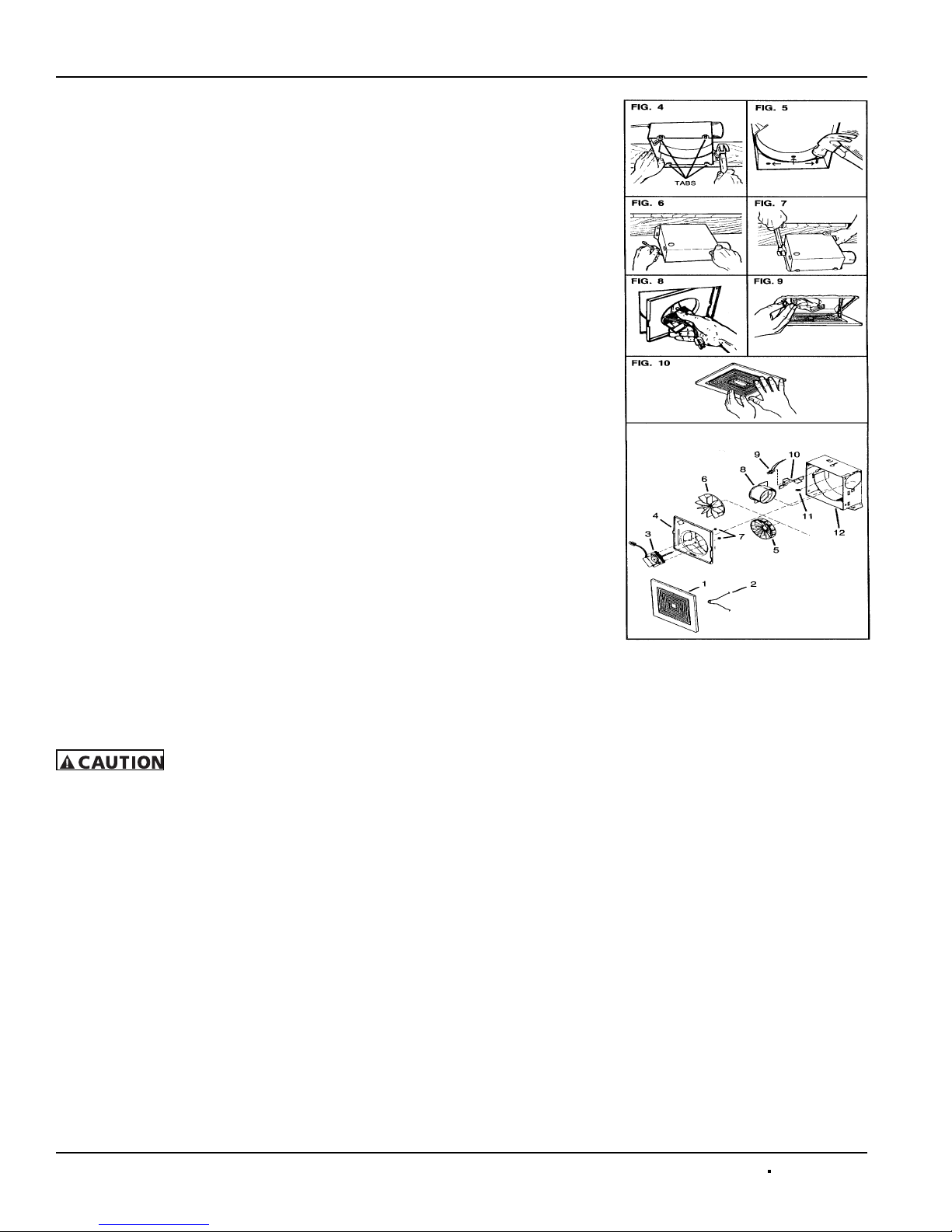
provide extra stability (Figure 4).
5b. Replacement Installation:
Position housing so that it is
centered in existing opening. Make
sure the housing will be flush with
the finished ceiling or wall. After
making electrical and ductwork con-
nections (see steps 4, 5 and 6), nail
housing in place. Drive nails through
the housing where indicated by
arrows (Figure 5).
5c. New Installation in an existing
ceiling or wall:
From above ceiling or behind wall,
position housing against stud or
joist. Trace outline of housing on
ceiling or wall material. (Fig. 6) Set
housing aside and cut opening.
Place housing in opening such that
its bottom edge is flush with the fin-
ished ceiling or wall. 1/2" ceiling or
wall material: Bend tabs outward 90º
(use a screw drive if desired) to rest
on top of ceiling or wall material and
provide extra stability. Nail in place
using four nails to ensure a solid,
quiet installation (Figure 7).
6. Install 3" round duct onto damper/
duct connector. If rigid ductwork is
used, its seam should be positioned
at top of damper/duct connector.
Tape the joint and extend ducting to
a wall cap or roof cap. Make sure
the damper operates freely. Ceiling
or wall can now be finished.
7. Replace the motor plate removed
in step 1. Insert two motor plate tabs
into slots in housing and then pivot
motor plate up until the third tab on
plate snaps into matching slot in
housing. Make sure tabs hold motor
plate securely in place. Plug
in motor (Figure 8).
8. Squeeze grill springs together
and insert springs into slots in motor
plate (Figure 9). Push the grill up
against ceiling or wall (Figure 10).
Parts Replacement
If replacing parts, do so with properly
selected components which duplicate the
original parts correctly. Incorrectly sized
parts can damage the fan.
PARTS LIST
1. Grill Assembly (includes Grill Spring
part #2)
2. Grill Spring (2 are required)
3. Motor (Models: 670, 671,
688 and 689)
4. Motor Plate
5. Blower Wheel
(Models 670 and 671)
6. Blower Wheel
(Models 688 and 689)
7. Nut #6-32 (2 are required)
8. Damper/Duct Connector
9. Receptacle
10. Wiring Cover
11. Housing Assembly

Operation & Maintenance Manual
Zephyr Ceiling/Wall Ventilating Fans Model Z1
Troubleshooting Checklist
Note: Care should be taken to follow all local electrical, safety and building codes. Provisions of the National Electric Code (NEC), as wells as the Occupational Safety
and Health Act (OSHA) should be followed.
All motors are checked prior to shipment. If motor defects should develop, prompt service can be obtained from the nearest author-
ized service station of the motor manufacturer while under warranty. Exchange, repair or replacement will be provided on a no
charge basis if the motor is defective within the warranty period. The PennBarry representative in your area will provide a name and
address of an authorized service station if requested. WARNING: Motor guarantee is void unless overload protection is provided in
motor wiring circuit.
PENNBARRY 3
1401 North Plano Road, Richardson, Texas 75081
Phone: 972-234-3202 Fax: 972-497-0468
Symptom Possible Cause(s) Corrective Action
Excessive noise
1. Defective or loose motor bearings 1. Replace motor with same frame size, RPM, HP
2. Ventilator base not securely anchored 2. Reset properly
3. Loose or unbalanced wheel/propeller 3. Tighten screws, remove build-up,
balance wheel/propeller
4. Misaligned pulleys or shaft 4. correct alignment
5. Loose or damaged wheel/propeller 4. Replace wheel/propeller
6. Wheel running in wrong direction 6. Reverse direction
Fan inoperative
1. Blown fuse or open circuit breaker 1. Replace fuses or circuit breaker
2. Loose or disconnected wiring 2. Shut off power and check wiring
for proper connections
3. Defective motor 3. Repair or replace motor
4. Broken belts 4. Replace belts
Insufficient airflow
1. Open access doors or loose sections of ducts 1. Check for leakage
2. Clogged filters 2. Clean filters
3. Operation in wrong direction 3. Correct rotation of wheel/propeller
4. Insufficient make-up air direction 4. Add make-up fan or louver opening
Water leaking
into ductwork or
collection of grease
under fan
1. Fan installed with slope in the wrong direction
1. Slope should be fitted in the direction of the
drainage opening or grease collection box and
drain spout
2. Clogged drain spout 2. Clean drain spout
3. Cooling tube or motor dome top removed 3. Install new cooling tube
with gasket and dome top
4. Grease container full 4. Empty grease box
Motor overheating
1. Belt slippage 1. Adjust tension or replace bad belts
2. Overvoltage or under voltage 2. Contact power supply company
3. Operation in wrong direction 3. Reverse direction of motor
4. Fan speed too high 4. Slow down fan by opening variable pitch
pulley on motor shaft
5. Incorrect motor (service factor 1.0,
low ambient temperature)
5. Replace motor with correct open,
NEMA service factors (1.15 or higher)
with 40 degrees ambient
6. Blocked cooling tube or leaky gasket 6. Remove blockage and seal cooling tube in place
7. Insufficient airflow to kitchen hood fan operating
on low speed with kitchen in full operation
7. Check airflow under hood and adjust
kitchen equipment output
8. Undersized motor 8. Check motor ratings with catalog speed
and air capacity chart

Operation & Maintenance Manual Zephyr Ceiling/Wall Ventilating Fans Model Z1
4 PENNBARRY 1401 North Plano Road, Richardson, Texas 75081
Phone: 972-234-3202 Fax: 972-497-0468
Limited Warranty
What Products Are Covered
PennBarry Fans and Ventilators (each, a "PennBarry Product")
One Year Limited Warranty For PennBarry Products
PennBarry warrants to the original commercial purchaser that the PennBarry Products will be free from defects in material and
workmanship for a period of one (1) year from the date of shipment.
Exclusive Remedy
PennBarry will, at its option, repair or replace (without removal or installation) the affected components of any defective PennBarry
Product; repair or replace (without removal or installation) the entire defective PennBarry Product; or refund
the invoice price of the PennBarry Product. In all cases, a reasonable time period must be allowed for warranty
repairs to be completed.
What You Must Do
In order to make a claim under these warranties:
1. You must be the original commercial purchaser of the PennBarry Product.
2. You must promptly notify us, within the warranty period, of any defect and provide us with any substantiation
that we may reasonably request.
3. The PennBarry Product must have been installed and maintained in accordance with good industry practice
and any specific PennBarry recommendations.
Exclusions
These warranties do not cover defects caused by:
1. Improper design or operation of the system into which the PennBarry Product is incorporated.
2. Improper installation.
3. Accident, abuse or misuse.
4. Unreasonable use (including any use for non-commercial purposes, failure to provide reasonable and necessary
maintenance as specified by PennBarry, misapplication and operation in excess of stated performance characteristics).
5. Components not manufactured by PennBarry.
Limitations
1. In all cases, PennBarry reserves the right to fully satisfy its obligations under the Limited Warranties by
refunding the invoice price of the defective PennBarry Product (or, if the PennBarry Product has been discontinued,
of the most nearly comparable current product).
2. PennBarry reserves the right to furnish a substitute or replacement component or product in the event a PennBarry
Product or any component of the product is discontinued or otherwise unavailable.
3. PennBarry's only obligation with respect to components not manufactured by PennBarry shall be to pass through
the warranty made by the manufacturer of the defective component.
General
The foregoing warranties are exclusive and in lieu of all other warranties except that of title, whether written, oral or
implied, in fact or in law (including any warranty of merchantability or fitness for a particular purpose).
PennBarry hereby disclaims any liability for special, punitive, indirect, incidental or consequential damages, including
without limitation lost profits or revenues, loss of use of equipment, cost of capital, cost of substitute products, facilities
or services, downtime, shutdown or slowdown costs.
The remedies of the original commercial purchaser set forth herein are exclusive and the liability of PennBarry
with respect to the PennBarry Products, whether in contract, tort, warranty, strict liability or other legal theory shall not exceed
the invoice price charged by PennBarry to its customer for the affected PennBarry Product at the time the claim is made.
Inquiries regarding these warranties should be sent to: PennBarry, 1401 North Plano Road, Richardson, TX 75081.
Table of contents
Other PennBarry Fan manuals

PennBarry
PennBarry Breezeway User manual

PennBarry
PennBarry ZQ105 User manual

PennBarry
PennBarry Muffan FS Manual

PennBarry
PennBarry DYNAMO Manual

PennBarry
PennBarry ZephyrZL1 Manual

PennBarry
PennBarry ZQ2005N User manual

PennBarry
PennBarry Fumex User manual

PennBarry
PennBarry MXI Series Manual

PennBarry
PennBarry RAU User manual

PennBarry
PennBarry ZQ405 User manual
Popular Fan manuals by other brands

ELTA FANS
ELTA FANS H03VV-F installation guide

Hunter
Hunter 20714 Owner's guide and installation manual

Emerson
Emerson CARRERA VERANDA CF542ORB00 owner's manual

Hunter
Hunter Caraway Owner's guide and installation manual

Panasonic
Panasonic FV-15NLFS1 Service manual

Kompernass
Kompernass KH 1150 operating instructions


