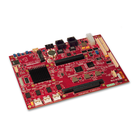
NXP Semiconductors i.MX 8M Plus User manual

i.MX 8M Plus Power Measurement Board
User's Guide
NXP Semiconductors Document identifier: IMX8MPPBUG
User's Guide Rev. 0, 29 April 2021

Contents
Chapter 1 Introduction........................................................................................... 3
Chapter 2 Board overview..................................................................................... 4
Chapter 3 Getting started.......................................................................................9
Chapter 4 Revision history...................................................................................20
NXP Semiconductors
i.MX 8M Plus Power Measurement Board User's Guide, Rev. 0, 29 April 2021
User's Guide 2 / 21

Chapter 1
Introduction
This is the user’s guide for the 8MPLUSLPD4-PEVK board based on the i.MX 8M Plus applications processor. It includes the
hardware/software setup and configurations and detailed information on the overall design.
NXP Semiconductors
i.MX 8M Plus Power Measurement Board User's Guide, Rev. 0, 29 April 2021
User's Guide 3 / 21

Chapter 2
Board overview
The 8MPLUSLPD4-PEVK consists of two separate boards: 8MPLUSLPD4-PWR (CPU board that supports power measurement)
and 8MPLUS-BB (Base Board). It is software-compatible with the 8MPLUSLPD4-EVK. The 8MPLUSLPD4-PEVK board can
measure 27 power rails, including 7 power rails that have dual-range options, for low-power measurement. All PHY power rails
are separated for measurement, so you can conveniently obtain the power consumption for each analog PHY.
2.1 Power rails
Table 1 lists the detailed information of the tested rails.
Table 1. Power rails under measurement
NO. Seq. Power rail
Operating range (V) Monitor
number
Range1
(mA)
Rs1
(OHM)
Range2
(mA)
Rs2
(OHM)
Min Normal Max
1 C 1 VSYS_5V
- M2
5000 0.02 238 0.42
2 J 2 NVCC_SNVS_1V8 1.65 1.8 1.950
M4
10 10 0.2 509
3 D
3
VDD_SOC 0.9 0.95 1
M2
10000 0.01 100 1.01
4 T
VDD_PLL_ANA_0V8 0.9 0.95 1 M7
100 1
- -
5 W
VDD_HDMI_0V8 0.9 0.95 1 M7 100 1 - -
6 V
VDD_MIPI_0V8 0.9 0.95 1 M7 100 1 - -
7 U
VDD_PCI_0V8 0.805 0.85 0.9 M7 100 0.4 - -
8 Y
VDD_USB_0V8 0.9 0.95 1 M8
250 0.4
- -
9 A 4 VDD_ARM 0.95 1 1.05
M1
5000 0.02 20 5.01
10 O
5
VDD_PLL_ANA_1V8 1.71 1.8 1.89
M5
400 1.008 9.1 11
11 K
VDD_EARC_1V8 1.71 1.8 1.89 M4 50 2 - -
12 I
VDD_HDMI_1V8 1.71 1.8 1.89 M4 50 2 - -
13 H
VDD_LVDS_1V8 1.71 1.8 1.89 M4
100 1
- -
14 N
VDD_MIPI_1V8 1.71 1.8 1.89 M5 50 2 - -
15 M
VDD_PCI_1V8 1.71 1.8 1.89 M5
100 1
- -
16 L
VDD_USB_1V8 1.71 1.8 1.89 M5 50 2 - -
17 R
6
CPU_VDD_1V8 1.65 1.8 1.95 M6 1000 0.1 - -
18 P
NVCC_SD1 1.65 1.8 1.95 M6 1000 0.1 - -
Table continues on the next page...
NXP Semiconductors
i.MX 8M Plus Power Measurement Board User's Guide, Rev. 0, 29 April 2021
User's Guide 4 / 21

Table 1. Power rails under measurement (continued)
NO. Seq. Power rail
Operating range (V) Monitor
number
Range1
(mA)
Rs1
(OHM)
Range2
(mA)
Rs2
(OHM)
Min Normal Max
19 Q
LPD4_VDD1 1.7 1.8 1.95 M6 20 4.99 - -
20 S
BB_VDD_1V8 1.65 1.8 1.89 M6 2000 0.05 - -
21 B
7
NVCC_DRAM_1V1 1.045 1.1 1.155
M1
2000 0.05 48.8 2.05
22 E LPD4_VDDQ 1.06 1.1 1.17
M3
2000 0.05 48.8 2.05
23 F
LPD4_VDD2 1.06 1.1 1.17 M3
2000 0.05
- -
24 X
8
VDD_USB_3V3 3.069 3.3 3.63 M8 100 1 - -
25 Z
VDD_SD1_3V3 2.7 3.3 3.6 M8 400 0.25 - -
26 a
BB_VDD_3V3 3 3.3 3.6 M8 2000 0.05 - -
- 9
BB_VSD_3V3 - - - - - -
27 G 10
NVCC_SD2 1.65 1.8 1.95 M3 100 1 - -
Note:
1.
The content in italics
means that the power rails can support dual-range measurement.
2.
Sensing resistance and range values correspond to values populated on 8MPLUSLPD4-PWR board revision A1. See
the latest schematic for detailed information.
3.
The Rs2 value is calculated by adding a low shunt resistor and a high shunt Rs1. See the latest schematic for detailed
information.
2.2 Power tree
Figure 1 shows the power tree of the PWR CPU board. The PWR board (8MPLUSLPD4-PWR) supply design is identical to the
standard CPU board (8MPLUSLPD4-CPU) but with current sense resistors of a suitable value inserted between the PMIC and
CPU for each key power rail measurement.
NXP Semiconductors
Board overview
i.MX 8M Plus Power Measurement Board User's Guide, Rev. 0, 29 April 2021
User's Guide 5 / 21

Figure 1. 8MPLUSLPD4-PWR board power tree
2.3 Power groups
There are four power groups defined on the 8MPLUSLPD4-PWR board:
•GROUP_SOC: i.MX 8MP SoC power consumption, including SOC PHY’s contribution.
•GROUP_SOC_FULL : Full i.MX8MP SoC power consumption, including PHY’s and IO’s contribution.
•GROUP_DRAM: DRAM device power consumption.
•GROUP_PLATFORM: Full platform consumption. This power group covers the power consumption of all components
supplied by the PMIC, including PMIC’s own consumption.
Table 2 lists the specific power rails included in the groups. These power groups can be monitored by the supported power
measurement applications.
NXP Semiconductors
Board overview
i.MX 8M Plus Power Measurement Board User's Guide, Rev. 0, 29 April 2021
User's Guide 6 / 21

Table 2. Power groups definition
Power group Power rail
GROUP_PLATFORM
(VSYS_5V rail)
GROUP_SOC_FULL
GROUP_SOC
NVCC_SNVS_1V8
VDD_SOC
VDD_ARM
NVCC_DRAM_1V1
VDD_PLL_ANA_0V8
VDD_HDMI_0V8
VDD_MIPI_0V8
VDD_PCI_0V8
VDD_USB_0V8
VDD_PLL_ANA_1V8
VDD_EARC_1V8
VDD_HDMI_1V8
VDD_LVDS_1V8
VDD_MIPI_1V8
VDD_PCI_1V8
VDD_USB_1V8
VDD_USB_3V3
i.MX8MP IO power
CPU_VDD_1V8
NVCC_SD1
NVCC_SD2
GROUP_DRAM
LPD4_VDD1
LPD4_VDDQ
LPD4_VDD2
Other component’s power supplied by PMIC
BB_VDD_1V8
BB_VDD_3V3
NXP Semiconductors
Board overview
i.MX 8M Plus Power Measurement Board User's Guide, Rev. 0, 29 April 2021
User's Guide 7 / 21

2.4 Board view
The overview of the 8MPLUSLPD4-PEVK platform is shown in Figure 2. It is fully software compatible with the 8MPLUSLPD4-EVK
platform. The difference between the two platforms is only the addition of the power measurement function on the 8MPLUSLPD4-
PEVK platform described in this document. To get more information about the common features of the board, see the
i.MX 8M
Plus LPDDR4 EVK Board Hardware User's Guide
(document IMX8MPEVKHUG).
Figure 2. 8MPLUSLPD4-PEVK platform
NXP Semiconductors
Board overview
i.MX 8M Plus Power Measurement Board User's Guide, Rev. 0, 29 April 2021
User's Guide 8 / 21

Chapter 3
Getting started
3.1 Power measurement acquisition applications
The following two applications are available to acquire real-time power data from the board, both are publicly available on GitHub:
•BCU software: Command-line tool
•PMT software: GUI-based tool
The BCU software is a command-line tool, designed to control boards/platforms that support remote control and power
measurement. It provides functions such as on/off key operation, board reset, setting boot mode, JTAG debug, and power
measurement through the USB debug port.
The PMT software is a GUI-based tool. It offers functionalities similar to the BCU, but thanks to the GUI, it also allows real-time
profiling of power rails (graphical monitoring of power, voltage, and current).
The sampling rate achieved on the BCU is higher than on the PMT due to the GUI processing on the latter.
• BCU is therefore provided for power acquisition where fine live monitoring is not the primary purpose, e.g. remote
acquisition, thanks to its higher sampling rate.
• PMT is therefore provided for live power monitoring activities during system design, debug phases, and also post-
processing analysis, thanks to its enhanced GUI.
Note that power acquisitions made using the BCU can be imported into the PMT for post-processing analysis to benefit from
the advantages of the two applications, higher sampling resolution of the BCU, and enhanced visibility of power rail activities of
the PMT.
This document only shows the power measurement functions for the 8MPLUSLPD4-PEVK platform. For more information on the
other functions of BCU and PMT, see the BCU release note in
GitHub
and
i.MX Power Measurement Tool
(document AN13119).
3.2 EEPROM configuration and usage
3.2.1 Description
The 8MPLUSLPD4-PWR board embeds a 32-kb System ID EEPROM (U28), connected to the I2C debug interface. This
EEPROM is used to store the following useful board information:
• Board ID and revision
• SoC ID and revision
• PMIC ID and revision
• Number of measurable power rails on the board
• Board serial number (user-defined)
The PMT and BCU power measurement acquisition tools can detect the type of the board connected by reading the EEPROM.
If the connected board is used for the first time, ensure that the EEPROM is correctly programmed. EEPROMs
are programmed during the board-manufacturing process. You can reset the configuration if an error occurs. The
current manufacturing EEPROM configuration settings are listed in the "Data" column in Table 3 (it is subject to
change in the case of 8MPLUSLPD4-PWR board revision updates).
NOTE
NXP Semiconductors
i.MX 8M Plus Power Measurement Board User's Guide, Rev. 0, 29 April 2021
User's Guide 9 / 21

3.2.2 EEPROM configuration
Table 3 shows all the useful information about the board stored in the EEPROM. The default manufacturing settings are indicated
in the "Data" column. The EEPROM configuration settings can be updated using the BCU or PMT tools, e.g. to set a new
board-specific serial number value (BOARD_SN).
Table 3. Board configuration data
Information Address of
EEPROM Data1Comments
BOARD_ID 0x1A NXP i.MX8MP EVK
PWR Board
These two information are very important.
Ensure that they are set properly in the PMT YAML
configuration file.
In the BCU, provide the correct [-brev=] value in the
command if you do not use the default revision value.
Note: A1 is the latest board release to be adapted to your
board version.
BOARD_REV 0x1C A1
SOC_ID 0x1D i.MX8MP This is related to the [-board=] option and it cannot be
changed manually in the BCU.
SOC_REV 0x1E A1
In the BCU, provide the correct [-srev=] value in the
command if you do not use the default revision value.
Note: A1 is the latest SoC revision to be adapted to your
SoC board revision.
PMIC_ID 0x1F PCA9450CHN
These are related to the [-board=] option and they cannot
be changed manually in the BCU.
PMIC_REV 0x20 N/A
NBR_PWR_RAILS 0x21 27
BOARD_SN 0x22 1 Board-specific serial number, user-defined
(range: 1~65535).
1.
EEPROM manufacturing current default settings
3.2.2.1 EEPROM configuration in PMT
To program the EEPROM with the PMT application, use the “EEPROM_Programmer_Tool” YAML file provided in the GitHub
PMT repository.
Complete the fields as follows:
• BOARD_ID: NXP i.MX8MP EVK PWR board
• BOARD_REV: A1
• SOC_ID: i.MX8MP
• SOC_REV: A1
• PMIC_ID: PCA9450CHN
• PMIC_REV: NOT FOUND
• NBR_PWR_RAILS: 27
• BOARD_SN: 24
NXP Semiconductors
Getting started
i.MX 8M Plus Power Measurement Board User's Guide, Rev. 0, 29 April 2021
User's Guide 10 / 21
Other manuals for i.MX 8M Plus
1
Table of contents
Other NXP Semiconductors Single Board Computer manuals