nVent RAYCHEM Raystat Quick start guide

Raystat
Version 5 (EU)
PART 1 INSTALLATION MANUAL ............................................
PRODUCT OVERVIEW
INSTALLATION INSTRUCTIONS
1
EN INSTALLATION NOTES ......................................................... 8
DE INSTALLATIONSHINWEISE ................................................. 12
FR CONSIGNES D'INSTALLATION ............................................ 16
SV INSTALLATIONSANMÄRKNINGAR .................................... 20
NO INSTALLASJONSMANUAL .................................................. 24
FI ASENNUSTA KOSKEVAT HUOMAUTUKSET .................... 28
DK INSTALLATIONSBEMÆRKNINGER .................................... 32
NL INSTALLATIEOPMERKINGEN ............................................. 36
PL UWAGI DOTYCZĄCE MONTAŻU ......................................... 40
CZ POZNÁMKY K INSTALACI .................................................... 44
ZH 安装注意事项 ........................................................................... 48
RU УКАЗАНИЯ ПО МОНТАЖУ ................................................. 52
LT PASTABOS DĖL MONTAVIMO ............................................. 56
IT NOTE PER L’INSTALLAZIONE .............................................. 60
PART 2 OPERATION MANUAL ...................................................
PROGRAM START - QUICK GUIDE
DISPLAY
PARAMETER SETTING
64
PART 3 ELECTRICAL SCHEME .................................................. 84
8 | nVent.com/RAYCHEM
1.3 INSTALLATION NOTES
The installation and, if necessary, the maintenance and the disassembling must be
carried out by a qualied electrical installer.
The installation must be compatible with local regulations.
Check the maximum circuit length for your circuit breaker in the next table:
Maximum circuit length at 230 VAC and for 5°C start-up temperature
C-characteristic circuit breaker
Multiple units on multiple power points can be used if longer heating cables are
required. We recommend to use nVent RAYCHEM SBS-FP-xx16A panels to operate 3,
6, 9 or 12 heating circuits
10XL2-LH 15XL2-LH 26XL2-LH 31XL2-LH
Circuit breaker (Plum) (Green) (Blue) (Purple)
C 10A 128 m 96 m 73 m 57 m
C 13A 166 m 125 m 94 m 74 m
C 16A 204 m 153 m 116 m 91 m
C 20A 238 m 188 m 142 m 114 m
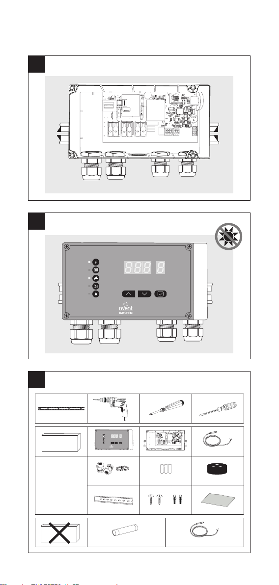
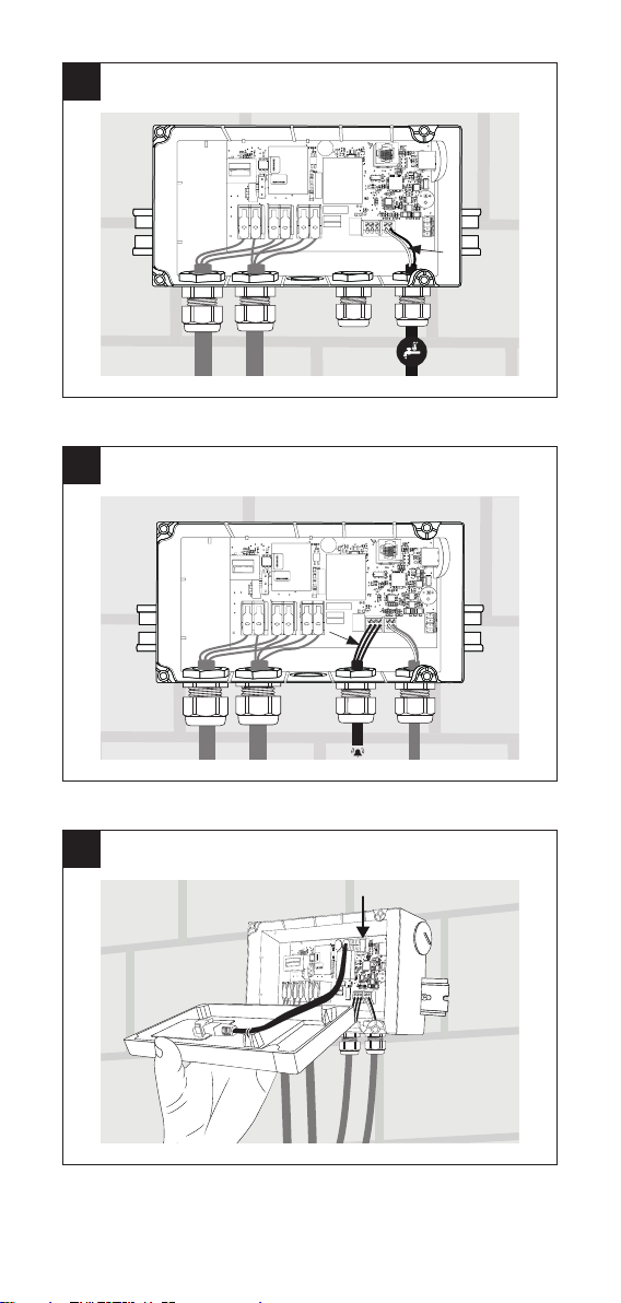
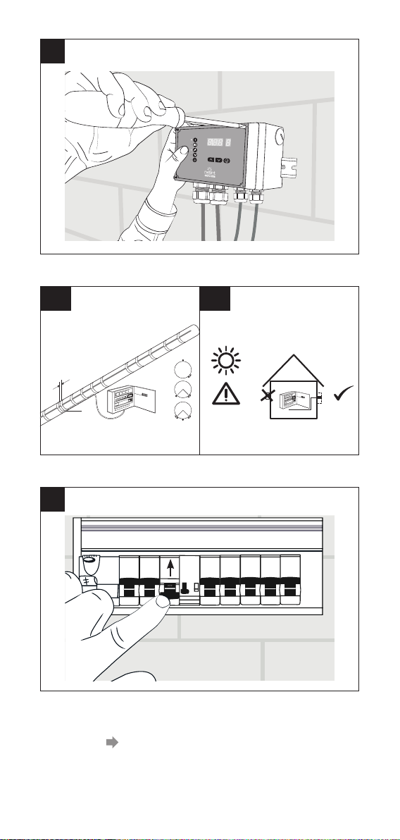
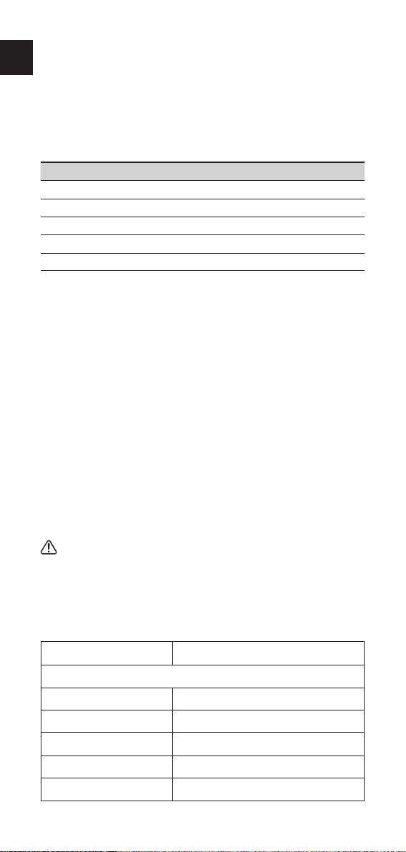
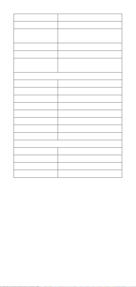
The nVent RAYCHEM Raystat V5 has a removable top lid. Both top and bottom of the box
have electronic parts and are connected to each other by an Ethernet connector cable.
The unit is delivered with top lid and back part dismantled.
Warning: For over voltage protection (e.g. in case of thunderstorm) we recommend
the use of an external over voltage protection device.
Care and maintenance
Clean the Raystat V5 with a soft damp cloth only, do not use any solvents. Do not
pour water directly on the device. Do not use a water hose or a high pressure cleaner.
Avoid installing the controller in rooms with high humidity and condensation. To
operate the user interface, it must be clean and dry. For outdoor installation it will be
recommended to use a sun & rain cover.
Description
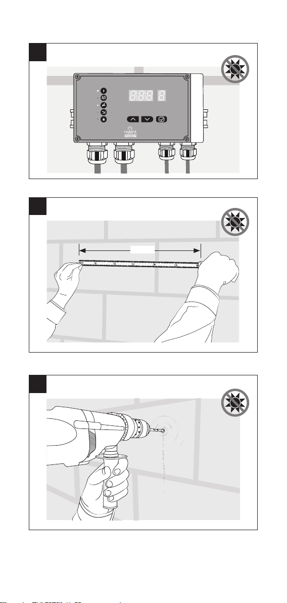
nVent RAYCHEM Raystat V5 is an electronic control thermostat with display,
advanced alarm facilities and the capability of switching large currents (25 A). The
Raystat V5 is designed to control nVent heating cable systems. Heating cable can be
controlled (switched ON/OFF) either directly by the Raystat V5 or via a contactor.
Direct switching of heating cables is possible for heating loads up to 25 A.
For heating loads above 25 A indirect switching via a suitably rated contactor con-
trolled by a Raystat V5 is necessary.
Installation and all wiring must be in accordance with applicable regulations.
The device must be installed in non hazardous areas only. nVent offers other controls
for use in hazardous areas.
The sensor must be installed. Attention: The sensor position on pipe or in Air
needs to match the operation mode PiPE or Air. (PASC / ambient temperature
measurement control). A wrong assignment can led to a frozen pipe.
An alarm terminal makes remote signalling of errors possible. During commissioning
of the unit it is recommend to simulate sensor functionality in PIPE sensing mode,
since the AIR/PASC mode is not suitable for this test due to delay in the PASC algo-
rithm. The unit can be pre-programmed in power-off mode by external power bank (to
be ordered separately) connected via A-A-USB cable and USB connection.
Technical data
Product application nVent RAYCHEM Pipe freeze protection heating
cables only
Electrical properties
Supply voltage 180-253 VAC; 50/60Hz
Power consumption 5,3 W max
Power output relay
(heating cable) 25 A / 230 VAC
Power supply terminals 3 x 6 mm² max
Heating cable terminals 3 x 6 mm² max
EN
nVent.com/RAYCHEM | 9
Alarm terminals 3 x 1,5 mm² max
Sensor terminal - Pipe 2 x 1,5 mm² max
Alarm relay
Single pole double throw relay, volt-free;
Max. switching capacity (resistive load only)
1 A/30 VDC 0.5 A/125 VAC, Max.: 60 VDC/
125 VAC
Settings All settings are stored in non-volatile memory
Operating temperature –40°C to +40°C ambient
Selectable temperature
PiPE: 0°C ... +90°C
(PT 100 Sensor Module: –40°C ... +250°C:
SM-PT100-1; PCN: 1244-022441)
Air (PASC): 0°C ... +30°C
Enclosure
Material Polycarbonate
Dimensions 210 mm x 90 mm x 85 mm
Ingress protection class IP 65
Weight 990 g
Mounting DIN-Rail mountable 35 mm
Entries 2 x M25 and 2 x M20
Storage temperature –40°C to +50°C
Flammability class D category (DIN EN 60730/VDE 0631-1)
Standard Sensor (included in the box)
Temperature sensor type Standard NTC 2,0 kOhm at 25°C, 2 wires
Sensor tip dimensions Ø 5 mm; length 20 mm
Sensor cable length 5 m; extendable up to 150 m , 2 x1,5 mm²
Temperature range –40°C to +90°C
10 | nVent.com/RAYCHEM
Sensor data Temperature Resistance in kOhm
–40°C 32,34
–35°C 24,96
–30°C 19,48
–25°C 15,29
–20°C 12,11
–15°C 9,655
–10°C 7,763
–5°C 6,277
0°C 5,114
+5°C 4,188
+10°C 3,454
+15°C 2,862
+20°C 2,387
+30°C 1,684
+40°C 1,211
+50°C 0,8854
+60°C 0,6587
+70°C 0,4975
+80°C 0,3807
Approval CE/UKCA mark; EMC According to EN 50081-
1/2 for emission and EN50082 - 1/2 for immu-
nity Temperature for ball pressure +100°C test
(DIN EN 60730/VDE 0631-1)
Rated impulse voltage: Overvoltage category III
(DIN EN 60730/ VDE 0631-1)
Sensor installation for higher temperature ranges:
For higher temperature ranges up to 250°C a PT100 type of sensor can be connected
by using the sensor-Plug-In Module SM-PT-100-1 (PCN: 1244-022441). A reset of
the unit is needed to recognize this new hardware module and to activate the new
temperature range.
Sensor
Standard With SM-PT-Module
(included in box) HARD- MONI-PT-/
Temperature sensor
type
NTC KOhm /
°C, -wire
PT PT
Sensor tip
dimensions
Ø mm,
length mm
Ø mm,
length mm
Ø mm,
length mm
Sensor cable length m m m
Cable extension Up to m, min.
x ,mm²
Up to m,
x ,mm²
Up to m,
x ,mm²
Temperature range —°C to +°C –°C to +°C –°C to +°C
OPERATION
The Raystat V5 has a LED user screen interface: The unit will switch to the main
screen after 2 minutes of non-interaction on the parameter input screens.
Quick install
When the unit is powered up for the rst time, a quick setup must be executed before
the unit is ready to start. The Quick start helps to set all important settings, the
unit will go in main screen mode automatically when done. Quick start is sufcient
for normal operations. More settings are available in the Setup menu for special
installation conditions.
The Quick start will only start if no pre-setting is done.
QUICK START 64
PARAMETER SETTING 71
Table of contents
Languages:
Other nVent RAYCHEM Thermostat manuals


Popular Thermostat manuals by other brands


Saswell
Saswell SAS920XWHB-7-S-RF User manual and warranty card

Aircalo
Aircalo TFP1-ET85P2 operating manual

Honeywell
Honeywell CM721 user manual

Carrier
Carrier DEBONAIR 33CS Installation and operating instructions

Lennox
Lennox iHarmony Zone Thermostat Installation and setup guide

Gemtech
Gemtech GT7000 Operation


