NewLine Raymor RAY1200CHR User manual

PRODUCT CODES:
RAY1200CHR
RAY1200WHT
INSTRUCTION MANUAL VERSION: 16/0001
Newline Group Limited
Freephone 0508 639 5463 | www.newline.co.nz
SLIDING
DOOR SET
INSTRUCTION MANUAL

PLEASE READ THROUGH AND UNDERSTAND ALL INSTRUCTIONS BEFORE
INSTALLATION AND USE.
CONTENTS PAGE
Important Information ... 1
Preparation Checklist ... 2
Supplied Components ... 3
Layout Procedure ... 5
Installation Steps ... 6
Newline Group Limited | Freephone 0508 639 5463 | www.newline.co.nz
CONTENTS

Page 1
Raymor Showers / Pivot Door Set
SLIDING DOOR SET / Important Information
IMPORTANT
When you receive your Raymor shower check contents for any freight damage. Advise
Newline on 0508 639 5463 if any damage has occurred within 8 hours of receiving the
goods so this is can rectied. Do not proceed with installation until resolved.
WARRANTY
Faulty goods are covered under warranty. Visit www.newline.co.nz for warranty information.
Breakages incurred during installation are not covered under warranty.
HEALTH AND SAFETY
Toughened Glass:
• Do not rework precut glass panels. Cutting or altering a glass panel will cause it to
explode without warning.
• Unpack all glass assemblies. Stand glass on soft packaging when it is on the oor
and against a wall. Care must be taken not to strike any edge or corner against a hard
surface as this will chip and destroy the glass panel.
Installation:
• Glass panels and assemblies are heavy. Two man lifting is recommended for handling
and installation.
• Determine positioning of wiring and piping within wall cavities before shower installation.
Mark their positions to ensure electrical and piping areas are avoided.
• Wear appropriate protective clothing and eye protection during installation.
TOOLS REQUIRED
Spirit Level Soft pencil Masking Tape
Electric Drill and Bits Tape measure
Square headed Screwdrivers Cleaning Materials and Rags
MATERIALS REQUIRED
Sika Silaex NG translucent Silicone.
AFTERCARE
The shower must be thoroughly cleaned weekly with a microber cloth, mild detergent and
water. Rinse with clean water and squeegee and wipe dry. Note: Glass panels are factory
pretreated with EnduroShield glass coating protection. Please visit enduroshield.com to
register your warranty and view cleaning and warranty requirements.
INSTALLATION
It is recommended that a professional shower installer is used to install this product.

Page 2
Raymor Showers / Pivot Door Set
PROJECT MANAGEMENT / Preparation Checklist
ENSURE YOU TICK THE SPECIFIC BOXES THAT APPLY AS YOU PROGRESS
2 Sided Shower: Ensure the oor is level and the walls are plumb and at.
Position all framing for solid xing for the shower tray, shower and plumbing ttings
(refer to the specic tray, liner and shower instruction manual at www.newline.co.nz).
Ensure all plumbing items have been installed prior to the lining being attached.
Alcove Shower: Critical that the walls are constructed plumb and at within the
specications of the specic shower being installed.
ACRYLIC TRAY AND LINER OPTION
• Detailed installation instructions are packed with the shower tray for tray and lining
installation.
• Alcove application may require specic detailing of framing or plasterboard lining. This
will need to be competed prior to framing.
• Shower waste and supply ttings must be installed by a registered plumber.
TILE INSTALLATION OPTION WITH STANDARD PROFINISHTM TILE TRAY
• The “ProFinishTM Tile Tray” must be installed as per the ProFinishTM installation
instructions with the packaged product.
• The leak proof waste and supply ttings must be installed by registered plumber.
• Waterproong must be undertaken by certied applicator and a Producer Statement
provided. There is a list of 14 proven systems listed in the back of these instructions.
• Tiling:
1. Manufacturers waterproong cure times must be adhered to.
2. The notched trowel lines for the tile mortar must be all leading to the waste outlet.
3. Ensure tiles are laid according to the falls in the tray.
4. The boundary line where the shower screen sits must be level.
5. Tile adhesive cure times must be allowed before commencing shower installation.

Page 3
Raymor Showers / Pivot Door Set
SUPPLIED COMPONENTS
Ref Description Parts Number Qty
1 Wall Posts 2
2 Screws M4x3/8" PACK 2
3 Screw Cover Caps PACK 12
4 Screws M4x1 3/8" PACK 16
5 Screws M4x5/16" PACK 12
6 Spacer Blocks 2
7 Return Panel 1
8 Handle Set 1
9 Top Rollers 2
10 Water Deectors 2
11 Door Panel 1
12 Bottom Rollers 2
13 Top/Bottom Rollers 2
14 Fixed Panels 1
15 Glass Clamp 2
Page 4
Raymor Showers / Pivot Door Set
LAYOUT PROCEDURE / 2Sided Shower
Shower Size Door Assembly Return Panel
1200mm x 900mm 1155mm (min) to 1175mm (max) 855mm (min) to 875mm (max)
Slide Shower Type Wall to Boundary Line
1200mm x 900mm 1165mm x 865mm
A
OTHER APPLICATIONS
• The smallest or largest measurement in this table may not be achievable if walls are
not plumb or the oor level.
MINIMUM TO MAXIMUM GUIDE
ACRYLIC TRAY APPLICATION
• Installation of the tray and liner must be completed as per
separate instructions pacakged with the Tray.
• Mark out the outside boundary line 22mm in from the
outside of the Tray (refer Diagram A). This measurement
will allow for walls out of plumb up to 8mm.
• Greater variances to plumb than 8mm at the wall must
be assessed and adjusted because this impacts on the
boundary line.
• Preferably the door and return panel boundary line
remains equal to the tray edge.
PROFINISHTM TILE TRAY WITH HOB APPLICATION
• Installation and completion of the framing, wall lining,
tray, waterproong and tiling must be complete. This is
covered in the ProFinishTM Instructions.
• The desired position for the boundary line is the 5mm
inwards of the centre line of the Hob.
• The Layout Table below will allow for approximately 8mm
of variation from plumb at the wall.
• Greater variances to plumb at the wall than 8mm must be assessed how this impacts
on the boundary line.
• Preferably the door and return panel boundary line remains equal to the tray edge.
Recommended measurement that can be used as a cross check for item 2:
22mm
A

22mm
2
2
Page 5
Raymor Showers / Pivot Door Set
INSTALLATION STEPS / 2Sided Conguration
STEP 1
1. Referring to the Assembly Layout Plan (Page 5), set up and plumb Wall Channels on
boundary line.
2. Apply silicone to back of wall channels and fasten to the wall ensuring that they remain
plumb.
Tiling Note: Some authorities do not allow the waterproof layer to be penetrated. Use
Bostik V60 to x Wall Channels and allow to cure as per manufacturers instructions.

Page 6
Raymor Showers / Pivot Door Set
STEP 2
Assembly of Door Frame
Components: Top and bottom rails (13) Fixed front panel (14) Corner post (17) Spacer
Blocks(6) 4 x 35mm screws (3) Two spacer Blocks (6) Two Glass clamps( 16) and 2
screws 4 x1 0mm. Note: Refer back to Assembly Drawing on page XX to reference
numbers.
1. Bring the Door Frame together as illustrated and with the 35mm screws and glass
clamps to secure to the frame.
2. Check the frame is square and tighten all fastenings.
3.

Page 7
Raymor Showers / Pivot Door Set
ALLOW 24 HOURS FOR
SILICONE TO DRY BEFORE
USE
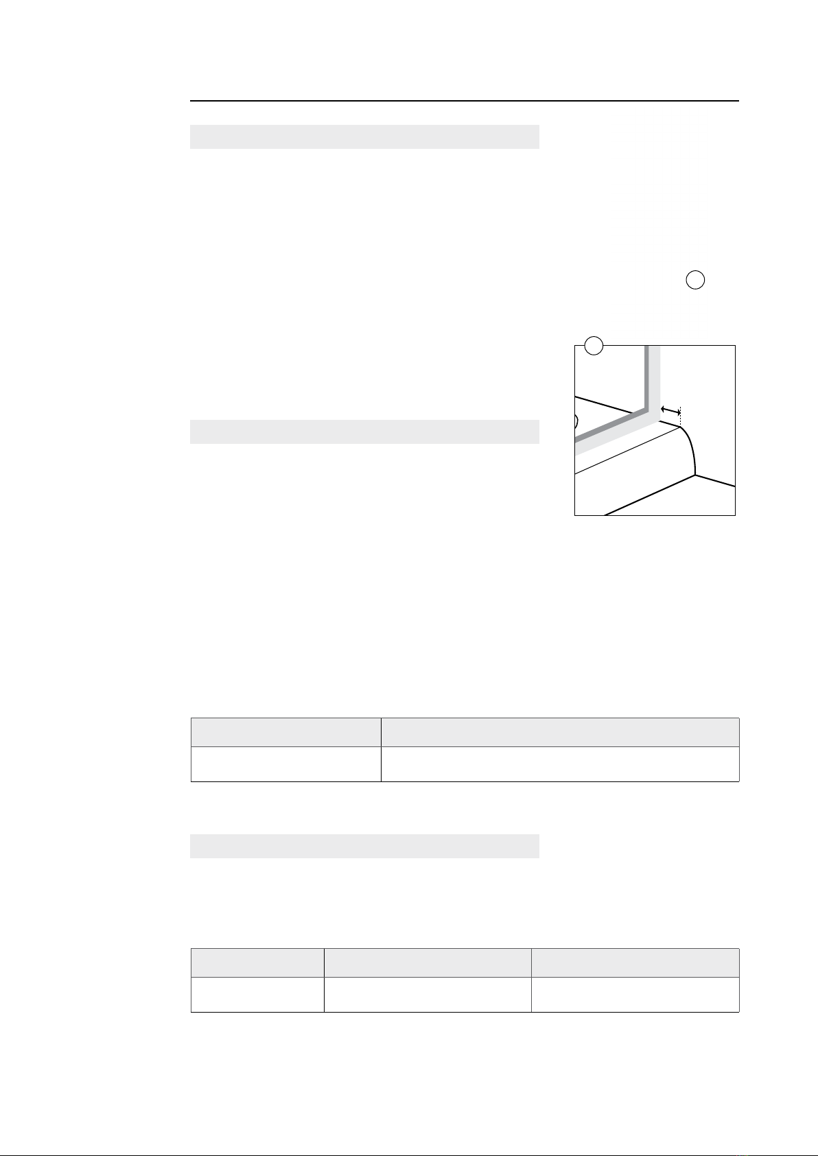
A
B
STEP 3
1. Slide Door assembly and Return panel into the wall channels. (1)
2. Bring together the two panel assemblies together at the corner (2).
3. Adjust the Door and Return Panels evenly on the tray and into the Wall channels (1).
4. Bring the corner joint together and drill and fasten this point (2).
5. Align the door frame and return panel evenly to the walls and Tray.
6. Square up the door frame.
7. Fit door inserting top rollers into top rail and push down bottom rollers into bottom rail.
8. Make nal alignment adjustments to the Shower with a spirit level and fasten frame to
Wall channels
STEP 4
1. Fasten the handle in place (A).
2. Apply silicone to the outer boundaries as indicated with dotted lines (B).
Note: Sealing on the inside of the shower will void the warranty.

Page 8
Raymor Showers / Pivot Door Set
LAYOUT PROCEDURE / Alcove Conguration
Shower Door Minimum Maximum
1200 (W) 1142mm 1182mm
OTHER APPLICATIONS
• Use the Minimum to Maximum Guide below to establish your outer boundary line.
• Wall or oor discrepancies will restrict use of the full range of minimum and maximum
measurements outlined below.
MINIMUM TO MAXIMUM GUIDE
ACRYLIC TRAY APPLICATION
• Installation of the tray and liner must be completed as per separate instructions.
• We recommend using GIB Aqualine® 13mm or equivalent for both sides of the Alcove.
This is optimum width.
• Measure outside boundary line at 15mm in from the outside of the Tray. Mark the tray
and plumb up the walls.
PROFINISHTM TILE TRAY WITH HOB APPLICATION
• Installation and completion of the framing, wall lining, tray, waterproong and tiling
must be complete. This is covered in the ProFinishTM Instructions.
• The nished width and depth of the framed and lined Alcove is 1190mm (W) x
900mm (D)
• Standard Raymor Slider Alcove“ProFinishTM Tray” size 1200 Tray =1190mm (W) x
900mm (D)
• Establish the Door Set outside boundary line at the centre position of the nished Tiled
Hob and plumb this up the walls.
This manual suits for next models
1
Table of contents
Other NewLine Bathroom Fixture manuals


