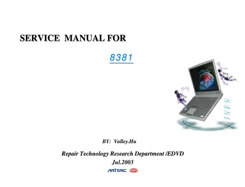
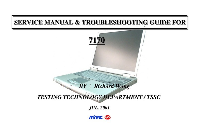
MiTAC 8175 User manual

SERVICE MANUAL FOR
8 1 7 5
8 1 7 58 1 7 5
8 1 7 5
SERVICE MANUAL FOR
SERVICE MANUAL FOR
8 1 7 5
8 1 7 58 1 7 5
8 1 7 5
8 1 7 5
8 1 7 58 1 7 5
8 1 7 5
TESTING TECHNOLOGY DEPARTMENT / TSSC
Apr . 2002
BY: Jacey
Jacey Liu
Liu

1
8175 N/B MAINTENANCE
1. Hardware Engineering Specification--------------------------------------------------------------------------------
CONTENTS
CONTENTS
1.1 Introduction--------------------------------------------------------------------------------------------------------------------------------
1.2 System Architecture----------------------------------------------------------------------------------------------------------------------
1.3 Electrical Characteristic-----------------------------------------------------------------------------------------------------------------
1.4 APPENDIX---------------------------------------------------------------------------------------------------------------------------------
1.5 BIOS Specification------------------------------------------------------------------------------------------------------------------------
2. System Assembly & Disassembly ------------------------------------------------------------------------------------
2.1 System View--------------------------------------------------------------------------------------------------------------------------------
2.2 System Disassembly----------------------------------------------------------------------------------------------------------------------
3. Definition & Location Connectors / Switches Setting -----------------------------------------------------------
3.1 Main Board---------------------------------------------------------------------------------------------------------------------------------
3.2 D/D Board-----------------------------------------------------------------------------------------------------------------------------------
3.3 Touch PAD Board-------------------------------------------------------------------------------------------------------------------------
3.4 Audio Board--------------------------------------------------------------------------------------------------------------------------------
4. Definition & Location Major Components-------------------------------------------------------------------------
4.1 Main Board---------------------------------------------------------------------------------------------------------------------------------
4.2 D/D Board----------------------------------------------------------------------------------------------------------------------------------
5. Pin Descriptions of Major Components ----------------------------------------------------------------------------
5.1 Pentium 4(Willamette/Northwood) Micro-FCPGA 478 pin----------------------------------------------------------------------
5.2 Intel 82845(Brookdale Memory Controller HUB)----------------------------------------------------------------------------------
5.3 Intel 82801BA(I/O Controller HUB )-------------------------------------------------------------------------------------------------
5.4 PCI4410(PCMCIA/1394 LINK Controller )----------------------------------------------------------------------------------------
4
4
5
22
32
39
81
81
85
103
103
106
107
109
109
111
112
112
118
125
130
108

2
8175 N/B MAINTENANCE
CONTENTS
CONTENTS
6. System Block Diagram -------------------------------------------------------------------------------------------------
7.1 Introduction--------------------------------------------------------------------------------------------------------------------------------
7.2 Error Codes--------------------------------------------------------------------------------------------------------------------------------
7.3 Debug Card--------------------------------------------------------------------------------------------------------------------------------
7. Maintenance Diagnostic ------------------------------------------------------------------------------------------------
8. Trouble Shooting --------------------------------------------------------------------------------------------------------
8.1 No Power------------------------------------------------------------------------------------------------------------------------------------
8.2 Battery Can not Be Charged-----------------------------------------------------------------------------------------------------------
8.3 No Display----------------------------------------------------------------------------------------------------------------------------------
8.4 VGA Controller Failure LCD No Display-------------------------------------------------------------------------------------------
8.5 VGA Controller Failure External Monitor No Display---------------------------------------------------------------------------
8.6 Memory Test Error-----------------------------------------------------------------------------------------------------------------------
8.7 Keyboard(K/B) and Touch Pad(T/B) Test Error-----------------------------------------------------------------------------------
8.8 Hard Drive Test Error-------------------------------------------------------------------------------------------------------------------
8.9 CD-ROM Drive Test Error-------------------------------------------------------------------------------------------------------------
8.10 USB Port Test Error--------------------------------------------------------------------------------------------------------------------
8.11 PIO Port Test Error---------------------------------------------------------------------------------------------------------------------
8.12 PC-Card Failure-------------------------------------------------------------------------------------------------------------------------
8.13 IEEE1394 Failure-----------------------------------------------------------------------------------------------------------------------
8.14 Audio Failure----------------------------------------------------------------------------------------------------------------------------
8.15 LAN Test Failure------------------------------------------------------------------------------------------------------------------------
9. Spare Parts List ----------------------------------------------------------------------------------------------------------
136
137
138
138
140
142
143
148
151
153
155
157
159
161
163
165
167
169
171
173
176
178

3
8175 N/B MAINTENANCE
CONTENTS
CONTENTS
10. System Explode View -------------------------------------------------------------------------------------------------
11. Circuit Diagram --------------------------------------------------------------------------------------------------------
12. Reference ----------------------------------------------------------------------------------------------------------------
190
191
218

4
8175 N/B MAINTENANCE
1.Hardware Engineering Specification
1.1 Introduction
1.1.1 General Description
This document describes the system hardware engineering specification for 8175 portable notebook computer system.
The 8175 notebook computer is a new mainstream high performance notebook in the MiTAC notebook family.
1.1.2 System Overview
CPU mPGA 478 -PIN Socket Support Intel Pentium (Willamette)/Northwood in mFC-PGA2 package
1. Dual independent Displays(LCD/CRT, LCD/TV,CRT/TV)
2. Support Motion Compensation and iDCT
3. Support Simultaneous display
Momory Two 144Pin SO-DIMM ,withont and on-board Memory
1. Support one slot of TypeII
2. Non Support Zoom video/Audio Function
IDE Support 2 IDE channel,Up to Ultra DMA 100
Support Dual 85MHz LVDS interface.
Support up to sXGA+ (1400*1050) Resolution
Button 5 Easy Start Button(functions defined by user)& 1 Mail Receive Button
LAN Support to 10/100 Based T
Modem 56Kbps V.90 MDC Modem
Pointing Glide PAD with 2 Buttons and 1 scroll button
Keyboard Internal Key Matrix Keyboard
BIOS 512KB Flash EEPROM (Include System BIOS&VGA BIOS)
Video
PCMCIA
LCD Display

5
8175 N/B MAINTENANCE
Audio 1. AC'97 Interface Codec. Sound Blaster Pro Compatible.
2. Built-In 21W speaker and 1 Mono-Microphone
1. Bi-Direction Parallel Port (EPP/ECP) 2. External VGA Port(D-SUB 15Pins)
3. 2 Standard USB 1.1 Port 4. SPIDF Jack
5. RJ-11 Port for Modem 6. Microphone In Jck
7. RJ-45 Port for LAN 8. VR for Audio Volume Control
9. DC Input Jack 10.Mini IEEE 1394 Port
11. S-Video Output Port(NTSC/PAL) 12. Battery Connector
Suspend Mode POS(S1), Suspend to RAM(S3), Suspend to Disk(S4)
Indicator HDD,FDD,CD-ROM,Num Lock,Caps Lock, Scroll Lock LEDs
I/O Port
1.2 System Architecture
1.2.1 Block Diagram(without Power System)

6
8175 N/B MAINTENANCE
8175 System Block Diagram

7
8175 N/B MAINTENANCE
1.2.2 Function Description
Socket Intel Pentium 4/ Northwood processors with 100MHz FSB.400MHz system bus.Capable of mFC-PGA2
package
1.2.2.1 CPU
Available at 1.50, 1.60, 1.70, 1.80, 1.90 and 2 GHz
Binary compatible with applications running on previous members of the Intel microprocessor line
Intel® NetBurst™ micro-architecture
System bus frequency at 400 MHz
Rapid Execution Engine: Arithmetic Logic Units (ALUs) run at twice the processor core frequency
Hyper Pipelined Technology
Advance Dynamic Execution
---Very deep out-of-order execution
---Enhanced branch prediction
Level 1 Execution Trace Cache stores 12K micro-ops and removes decoder latency from main execution loops
8 KB Level 1 data cache
256 KB Advanced Transfer Cache (on-die,full speed Level 2 (L2) cache) with 8-way associatively and Error
Correcting Code (ECC)
144 new Streaming SIMD Extensions 2 (SSE2) instructions
Enhanced floating point and multimedia unit for enhanced video, audio,encryption, and 3D performance
Power Management capabilities
---System Management mode
---Multiple low-power states

8
8175 N/B MAINTENANCE
Optimized for 32-bit applications running on advanced 32-bit operating systems
8-way cache associatively provides improved cache hit rate on load/store operations.
1.2.2.2 CORE LOGIC
Intel Brookdale 82845 Memory Control HUB
Intel® Pentium® 4 Processor (478 pin package) Support:
---Enhanced Mode Scaleable Bus Protocol
---2x Address, 4x Data
---System Bus interrupt delivery
---400 MHz system bus
---System Bus Dynamic Bus Inversion (DBI)
---32-bit system bus addressing
---12 deep In-Order Queue
---AGTL+ bus driver technology with integrated AGTL+ termination resistors
System Memory Support
---Directly supports one SDR SDRAM channel, 64 bits wide (72 bits with ECC)
---133 MHz SDR SDRAM devices
---64 Mb, 128 Mb, 256 Mb and 512 Mb technologies for x8 and x16 devices
---By using 64 Mb technology, the smallest memory capacity possible is 32 MB
---Configurable optional ECC operation (single bit Error Correction and multiple bit Error Detection)
---Page sizes of 2 KB, 4 KB, 8 KB and 16 KB (individually selected for every row)
---Thermal management
---Maximum of 3 Double-Sided DIMMs (6rows populated) with unbuffered PC133 (with or without ECC)
---3 GB Maximum using 512 Mb technology
---Supports up to 24 simultaneous open pages
---Maximum memory bandwidth of 1.067 GB/s with PC133

9
8175 N/B MAINTENANCE
Hub Interface to Intel® 82801BA ICH2
---266 MB/s point-to-point hub interface to ICH2
---66 MHz base clock
---MSI interrupt messages, power management state change, SMI, SCI and SERR error indication
Accelerated Graphics Port (AGP) Interface
--- Supports a single AGP device (either a connector or on the motherboard)
---Supports AGP 2.0 including 1x, 2x, and 4x AGP data transfers and 2x/4x Fast Write protocol
---Supports only 1.5 V AGP electrical characteristics
---32 deep AGP request queue
---Delayed transaction support for AGP-to-System Memory FRAME# semantic reads
System Interrupt Support
---System bus interrupt delivery mechanism
---Interrupts signaled as upstream memory writes from AGP/PCI
---Supports peer MSI between hub interface and AGP
---Provides redirection for IPI and upstream interrupts to the system bus
Power Management
---SMRAM space remapping to A0000h
---Supports extended SMRAM space above 256 MB, additional TSEG from Top of Memory
interface are not supported
---PC ’99 suspend to DRAM support
---ACPI, Revision 1.0b compliant power management
---APM, Revision 1.2 compliant power management
---NT Hardware Design Guide, Version 1.0 compliant
Package
---MCH: 593 pin FC-BGA (37.5 x 37.5 mm)
Table of contents
Other MiTAC Laptop manuals