
Miele DAS 4920 User manual

12062340-01
Installation
*INSTALLATION*
Before installation
Before installation, it is important
to read the information given on the
following pages as well as the
“Warning and Safety instructions” at
the beginning of this booklet.
Installation recommendations
- To achieve optimum vapour
extraction, the cooker hood must be
positioned centrally over the hob, not
to the side.
- The hob should be no wider than the
cooker hood, and if possible, it
should be narrower.
- The installation area must be easily
accessible. The cooker hood should
be easily accessible and easy to
dismantle in the event that service is
required. This should be taken into
consideration when planning the
position of cupboards, shelves,
ceilings or features in the vicinity of
the cooker hood.
Installation materials
1vent connection
for exhaust ducting 150mm.
1 non-return flap
for fitting into the exhaust socket on
the motor unit (not needed for
recirculation mode). Depending on the
model, the non-return flap may already
be fitted.
4mounting plates
for installation in a 600mm wide
cabinet
2 brackets
for installation in a 900mm wide
cabinet (only for 900mm wide
appliances)
2spring clips
for installation in a 900mm wide
cabinet (only for 900mm wide
appliances)
1spacer strip
for concealing the gap between the
rear of the appliance and the wall

12062340-01
Installation
*INSTALLATION*
4screws, M4x8mm
4 (8)* screws, 4x15mm
4screws, 4x30mm
8 (12)* screws, 4x15mm
4screws, M4x12mm*
4screws, M4x8.5mm*
* For 896mm wide appliances
Montage
Installation
Montaje
Montaggio
Montering
Montagem
Asennus
Installation plan
See the installation plan for details on
the individual steps involved in the
installation of this appliance.
11839970
DML2000 installation kit
for installing a hinged front panel to
match kitchen furniture units (not
supplied; available as an optional
accessory)
Installation materials for recirculation
mode
You need the following optional
accessories for recirculation mode:
DFKS31-x installation kit
contains 2holders and 2 charcoal
filters (DFKS31-P with single-use
charcoal filters or DFKS31-R with
reactivatable charcoal filters)
DUU15x installation kit
contains a directional unit socket, hose
and hose clips (DUU150 for the top of
the cabinet or DUU151 for the sides or
front of the cabinet)
12062340-01
Installation
*INSTALLATION*
Appliance dimensions
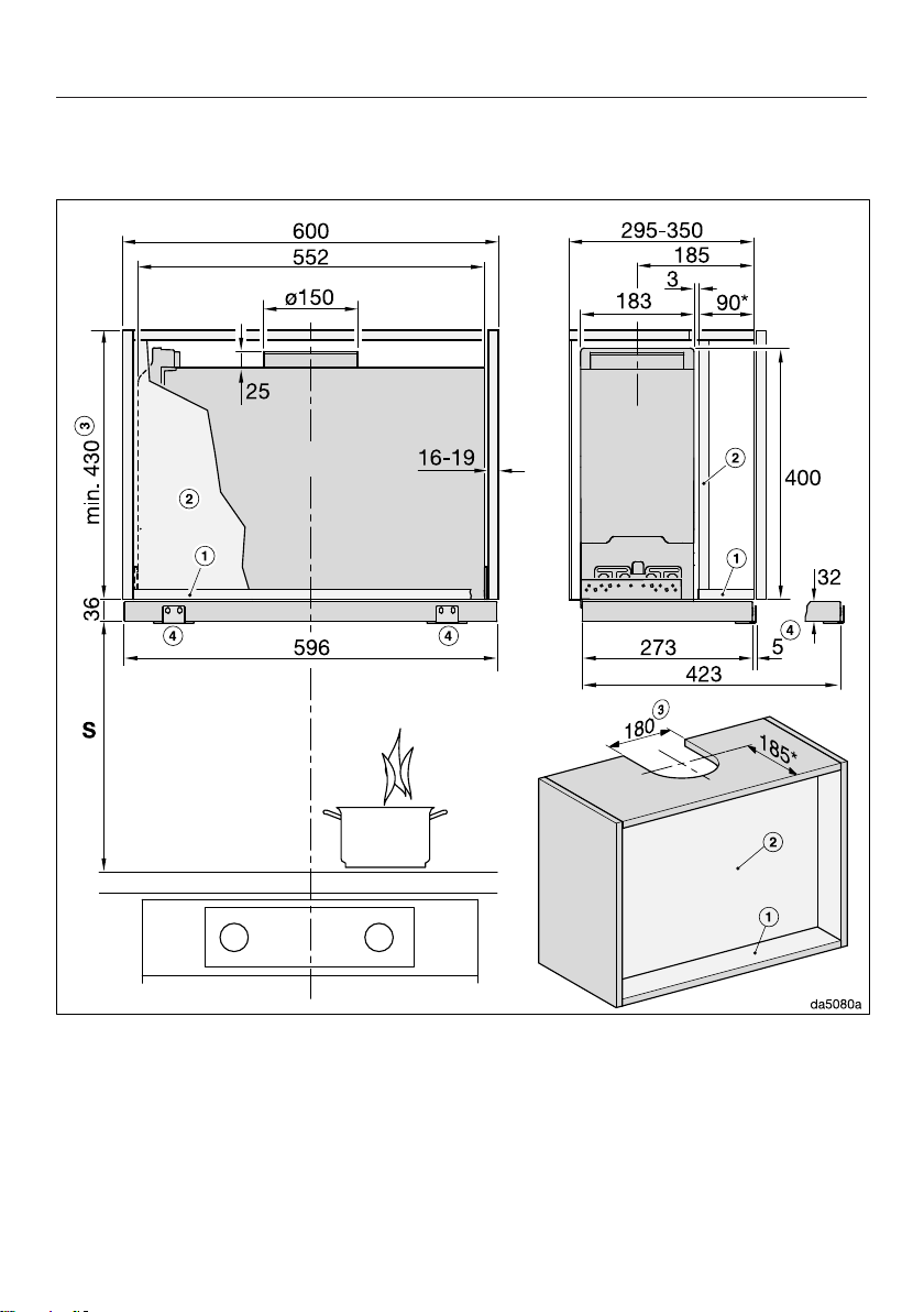
Dia. 1: DAS4620 in a 600mm wide cabinet.
The drawing is not to scale
12062340-01
Installation
*INSTALLATION*
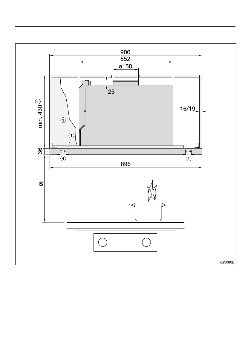
Dia. 2: DAS4920 in a 900mm wide cabinet.
The drawing is not to scale
See diagram 1 for side view

12062340-01
Installation
*INSTALLATION*
Dia. 3: DAS4920 in a 900mm wide cabinet or in a 900mm wide cabinet with side
compartments.
The drawing is not to scale
See diagram 1 for side view
Footnotes for diagrams 1to 3:
aThe front section of the cabinet must be fitted with a base panel to secure the
cooker hood.
bIf a partition wall is to be provided in the cabinet, it must be removable.
cExtraction or recirculation with conversion kit DUU150
dDML2000 bracket (optional accessory) for fitting a front panel
* In this installation situation, the deflector plate is flush with the front edge of the
housing unit carcase. If you wish to position the cooker hood further forward or
further back, you must adapt the dimensions accordingly (e.g. if you are using a
front panel).
The height of the cabinet and the cut-out dimensions must take into account any
accessories fitted (e.g. silencer, recirculation hood conversion kit)

12062340-01
Installation
*INSTALLATION*
Safety distance between hob and cooker hood (S)
When planning the installation height of your cooker hood, the minimum safety
distance between the top of a cooker or hob and the bottom of the cooker hood
is as follows, unless a greater distance is specified by the manufacturer of your
cooking appliance.
See “Warning and Safety” instructions for further information.
Cooking appliance Minimum distance S
Electric hob 450mm
Electric grill, deep fat fryer (electric) 650mm
Multi-burner gas hob,
total output ≤ 12.6 kW, no burner > 4.5 kW
650mm
Multi-burner gas hob,
total output > 12.6 kW and ≤ 21.6 kW,
no burner > 4.8 kW.
760mm
Multi-burner gas hob,
total output > 21.6 kW,
or multi-burner gas hob where one burner > 4.8 kW.
Not possible
Single burner gas hob, output ≤ 6 kW. 650mm
Single burner gas hob, output > 6 kW and ≤ 8.1 kW. 760mm
Single burner gas hob, output > 8.1 kW Not possible
If you are fitting a front panel made of wood or plastic to the cooker hood,
observe the safety distances given by the hob manufacturer regarding the use
of easily flammable materials.

12062340-01
Installation
*INSTALLATION*
Connection for air extraction
If the cooker hood is used at the
same time as a heating appliance
that relies on oxygen from the same
room, there is a risk in certain
circumstances of toxic fumes
building up.
It is essential that the “Warning and
Safety” instructions are observed.
The cooker hood should be installed
according to local and national
building regulations. Seek approval
from the building inspector where
necessary.
Only use smooth pipes or flexible
exhaust ducting made from
approved non-flammable materials
for exhaust ducting.
To achieve the most efficient air
throughput with the lowest noise levels,
please note the following:
- The diameter of the exhaust ducting
must not be smaller than the cross-
section of the exhaust duct (see
“Appliance dimensions”). This applies
in particular when using flat ducting.
- The exhaust ducting should be as
short and straight as possible.
- Only use wide radius bends.
- The exhaust ducting must not be
kinked or compressed.
- All connections must be strong and
airtight.
- If the exhaust ducting has flaps,
these must be opened whenever the
cooker hood is switched on.
Any constriction of the air throughput
will reduce extraction performance
and increase operating noise.
Flue
If the exhaust air is to be ducted into a
flue, the ducting must be directed in the
flow direction of the flue.
If the flue is used by several ventilation
units, the cross-section of the flue must
be large enough.

12062340-01
Installation
*INSTALLATION*
Non-return flap
Use a non-return flap in the exhaust
system.
A non-return flap ensures that when the
cooker hood is not in operation, the
duct is closed to prevent unwanted
exchange of room air and outside air.
If the exhaust is ducted through an
outside wall, a Miele wall vent or roof
vent (available as an optional
accessory) is recommended. Both of
these have a built-in non-return flap.
If the on-site ventilation system does
not have a non-return flap, one is
supplied with the cooker hood.
The non-return flap is fitted in the
exhaust socket of the fan.
Condensation
If the exhaust ducting is to run through
cool rooms or ceiling space, for
example, the significant variations in
temperature between the different areas
can cause condensation to form.
Insulate the exhaust ducting to reduce
temperature variations.
If the exhaust ducting is to be laid
horizontally, it must be laid with a
downwards sloping gradient of at least
1cm per meter. This is to ensure that
condensation cannot drain back into
the cooker hood.
In addition to insulating the exhaust
ducting, it is advisable to also install a
condensate trap for collecting and
evaporating any potential condensation.
Condensate traps for 125mm or
150mm diameter exhaust ducting are
available as optional accessories.
When installing a condensate trap,
ensure that it is positioned vertically
and as closely as possible to the cooker
hood above the exhaust connection.
The arrow on the casing indicates the
direction of airflow.
Miele shall not accept warranty claims
for any functional defects or damage
caused by inadequate exhaust
ducting.

12062340-01
Installation
*INSTALLATION*
Silencer
To reduce noise levels even further, a
silencer (optional accessory) can be
installed in the exhaust ducting.
In extraction mode, the silencer not only
reduces noise from the fan outside the
house, but also sounds originating
outside reaching the kitchen through
the exhaust ducting (e.g. traffic noise).
For this reason, the silencer must be
positioned as close as possible to the
ducting exit.
In recirculation mode, the silencer
needs to be positioned between the
exhaust vent and the exhaust grille.
Check that there is sufficient space.

12062340-01
Installation
*INSTALLATION*
Electrical connection
The cooker hood is supplied with a
mains cable with moulded plug ready
for connection to a suitable earthed
socket.
If the socket is not easily accessible or
a fixed connection is envisaged, ensure
that a suitable means of disconnection
is provided on the installation side for
each pole.
Risk of fire from overheating.
Connecting the cooker hood to
multi-socket adapters or extension
cables can overload the cables.
For safety reasons, do not use an
extension cable or multi-socket
adapter.
The electrical system must comply with
local and national safety regulations
(BS7671 in the UK).
For safety reasons, we recommend
using a type residual current device
(RCD) in the relevant electrical
installation for connecting the cooker
hood.
If the mains connection cable is
damaged, it must only be replaced with
a specific mains connection cable of
the same type (available from the Miele
Customer Service Department). For
safety reasons, such replacement may
only be carried out by a qualified
specialist or the Miele Customer
Service Department.
These operating instructions and the
data plate indicate the nominal power
consumption and the appropriate fuse
rating. Compare this information with
the data of the on-site electrical
connection.
If in any doubt, consult a qualified
electrician.
Temporary or permanent operation on
an autonomous power supply system or
a power supply system that is not
synchronised with the mains power
supply (e.g. island networks, back-up
systems) is possible. A prerequisite for
operation is that the power supply
system complies with the specifications
of EN50160 or an equivalent standard.
The function and operation of the
protective measures provided in the
domestic electrical installation and in
this Miele product must also be
maintained in isolated operation or in
operation that is not synchronised with
the mains power supply, or these
measures must be replaced by
equivalent measures in the installation.
As described, for example, in the
current version of VDE-AR-E 2510-2.
Other manuals for DAS 4920
2
This manual suits for next models
1
Table of contents
Other Miele Ventilation Hood manuals

Miele
Miele DA 3466 User manual

Miele
Miele DA 289 Parts list manual
Miele
Miele DA 6708 D User manual

Miele
Miele DA 3660 User manual

Miele
Miele DA 6996 W User manual

Miele
Miele PUR 98 D User manual

Miele
Miele DA 3466 User manual

Miele
Miele DA 3668 User manual

Miele
Miele TX3587 User manual

Miele
Miele DA 3568 User manual

Miele
Miele DA 6698 W User manual

Miele
Miele DA 5320 D User manual

Miele
Miele DAS 4720 User manual

Miele
Miele DA 6700 D User manual

Miele
Miele DA250-4 User manual

Miele
Miele DA 402 User manual

Miele
Miele DA 6796 W User manual

Miele
Miele DA 419-4 Specification sheet

Miele
Miele DA 409 User manual

Miele
Miele DA 5190 W User manual


