
Microtest 6235 User manual
6235+7721+7605
S/W Ver
Firmware Ver
Date
1.0
APR 2020
User Manual
3 in 1 Transformer Comprehensive Tester

1
+Safety Instructions
Please pay special attention to the safety instruction items described below when
operating and maintaining this machine. If these items and other warnings mentioned
inside this manual are not followed, it will be in serious violation of the safety
standards for the design, manufacture and operation of this instrument.
+Machine Maintenance Precautions
Operators must not remove the protective case of the instrument; only qualified
maintenance personnel are allowed to perform tasks including the replacing of
components inside the machine and internal adjustments etc. Do not change any
components when the power cable is already plugged into the socket. Under certain
special circumstances, there might still be dangerous voltage remaining even if the
power plug has already been unplugged from the power outlet. In order to avoid
causing injuries, disconnect the power and take the necessary discharge measures
before touching the inside of the instrument.
+Instrument Grounding
In order to prevent the danger of electric shock, please ground the power cable of the
instrument.
+Do not perform tasks such as maintenance or internal adjustments
alone
Do not perform tasks such as maintenance or internal adjustments alone.
+Do not change the components or modify the functions and
structures of the machine on your own
Without authorization from our company, do not install replacement components or
perform any modifications to this machine on your own in order to avoid increasing
the danger of the machine or causing damage to the machine. When the instrument
malfunctions, please send the instrument back to Microtest Corporation to have
professionals repair it for you in order to ensure its safety.
+Product Warranty Period
MICROTEST provides one-year warranty for this product starting from its shipping
date, but the warranty for some of the special components subject to the product
specifications and characteristics are not limited to this. Microtest Corporation will be
responsible for repairing or replacing products proven to be flawed (MICROTEST
will test whether the product was flawed or not) during the warranty period. Microtest
Corporation guarantees that the software and hardware used with the instrument can
execute their program instructions once they are properly installed on the instrument.
MICROTEST does not guarantee that no interruptions or errors will occur while
operating the software and hardware of the instrument.
+Product Warranty Restrictions
The warranty described above is not applicable to incorrect or improper use of this
product by the customer, modifications, maintenance or changing components of this
machine without authorization, or misuse of this product. In addition, warranty is not
provided for the storing and maintaining of this product in environments not within
the conditions specified.
Microtest Corporation all rights reserved.
Declaration: Microtest Corporation reserves the right to modify the contents of
this manual without further notice!

2
Chapter 1. Precautions.............................................................................................3
1.1 Electrification and Electric Shock .............................................................3
1.2 Static electricity .........................................................................................3
1.3 Ground .......................................................................................................3
1.4 Power .........................................................................................................3
1.5 Connect the testing cable to the high voltage output terminal...................4
1.6 Warm up.....................................................................................................4
1.7 External control host ..................................................................................4
1.8 Machine malfunction .................................................................................4
1.9 Test End......................................................................................................4
1.10 Placement and Storage...............................................................................4
1.11 Emergency Handling..................................................................................4
Chapter 2. Start ........................................................................................................5
2.1 Setting process ...........................................................................................5
2.2 How to set the hardware architecture.........................................................6
2.3 Precautions before booting up .................................................................12
Chapter 3. Operation..............................................................................................12
3.1 6235 System Settings...............................................................................12
3.2 7605 System Settings...............................................................................14
3.3 6235 test item creation .............................................................................14
3.3.1 Entering the main menu of test items .................................................15
3.3.2 WINDING/FIXTURE editing description...................................16
3.3.3 SEQUENCE / BIN editing description........................................17
3.3.4 L/Lk/Q/Rac/Z/D/Ø/X/Y test item editing description .................22
3.3.5 Rdc test item edit description.......................................................25
3.3.6 Turn Ratio test item editing description.......................................26
3.3.7 C test item editing ........................................................................27
3.3.8 BALANCE test item editing description .....................................28
3.3.9 PIN SHORT test item editing description....................................29
3.3.10 CORRECTION fixture correction ...............................................30
3.3.11 DEVIATION error compensation setting description..................31
3.4 7721 and 7605 test item setting ...............................................................32
3.4.1 Layer short-circuit and high voltage tester setting.......................32
3.5 Test program data and statistical data storage management ....................37

3
Chapter 1. Precautions
This tester outputs voltage as high as 6000V DC for external testing; accidents will
happen if this tester is used incorrectly or improperly. Therefore, in consideration of
your own safety, please read the precautions described in this chapter carefully and
memorize them in order to prevent accidents from occurring.
1.1 Electrification and Electric Shock
In order to prevent electric shock, the wearing of insulating plastic gloves is
recommended before using this tester to perform testing related tasks.
1.2 Static electricity
This instrument uses components that are very sensitive to static
◼The desktop of the worktable must be grounded conductive
material.
◼The contact of the soldering iron and tools must be connected to
grounded conductors when not in use.
◼Maintenance personnel must wear static bracelets with leakage
resistance less than 1MΩ
◼Components or the assembling substrate must be placed in
protective cases with static protection.
1.3 Ground
This is a safety ground terminal on the rear panel case of this tester. Please
ground this terminal properly in order to prevent electric shock accidents from
occurring when touching the case.
1.4 Power
Power cables that comply with the local country specifications must be used, and
connectors applicable to IEC320 connectors must be used for the connection of
this instrument. Users must ensure that the ground cable is properly grounded. If
the power plug includes a fuse, 3 ampere fuses that meet the safety regulations
must be used; confirm that it’s AC power before use and adjust the 115V/230V
power selection switch on the rear panel to let the machine match local power
voltages.

4
1.5 Connect the testing cable to the high voltage
output terminal
While the tester is powered off, insert the high voltage testing cables to the high
voltage output terminals on the tester respectively, and confirm that the exteriors
of the testing cables are not ruptured or shed.
1.6 Warm up
The tester can operate normally once the power is turned on; however, in order to
achieve the accuracy within specification, please turn on the machine in advance
and let it warm up for 30 minutes or more before use.
1.7 External control host
This tester can perform external control; make sure the operator is not touching
the high voltage output terminal and DUT when performing such controls in
order to avoid causing danger.
1.8 Machine malfunction
If it is discovered that this tester has malfunctioned, for example: the voltage
displayed on the voltmeter differs greatly from the voltage set, or there is no high
voltage output but the high voltage output warning indicator remains on etc.,
cease use immediately and contact our company or your dealer to perform
repairs.
1.9 Test End
Turn off the power switch when the tester is not being used.
1.10 Placement and Storage
The operating temperature and humidity range of this machine is 5oC - 40oC,
80% RH; the actions might be abnormal if this range is exceeded. The storage
temperature and humidity range of this machine is -20oC - 70oC, 80% RH. In
order to achieve accurate testing and for safety considerations, do not place this
machine in environments with direct sunlight exposure, high temperature, high
humidity, frequent vibrations or excessive dust.
1.11 Emergency Handling
When there is an electric shock or if the DUT or machine catches on fire, please
switch off the power and unplug the power cable.
5
Chapter 2. Start
2.1 Setting process
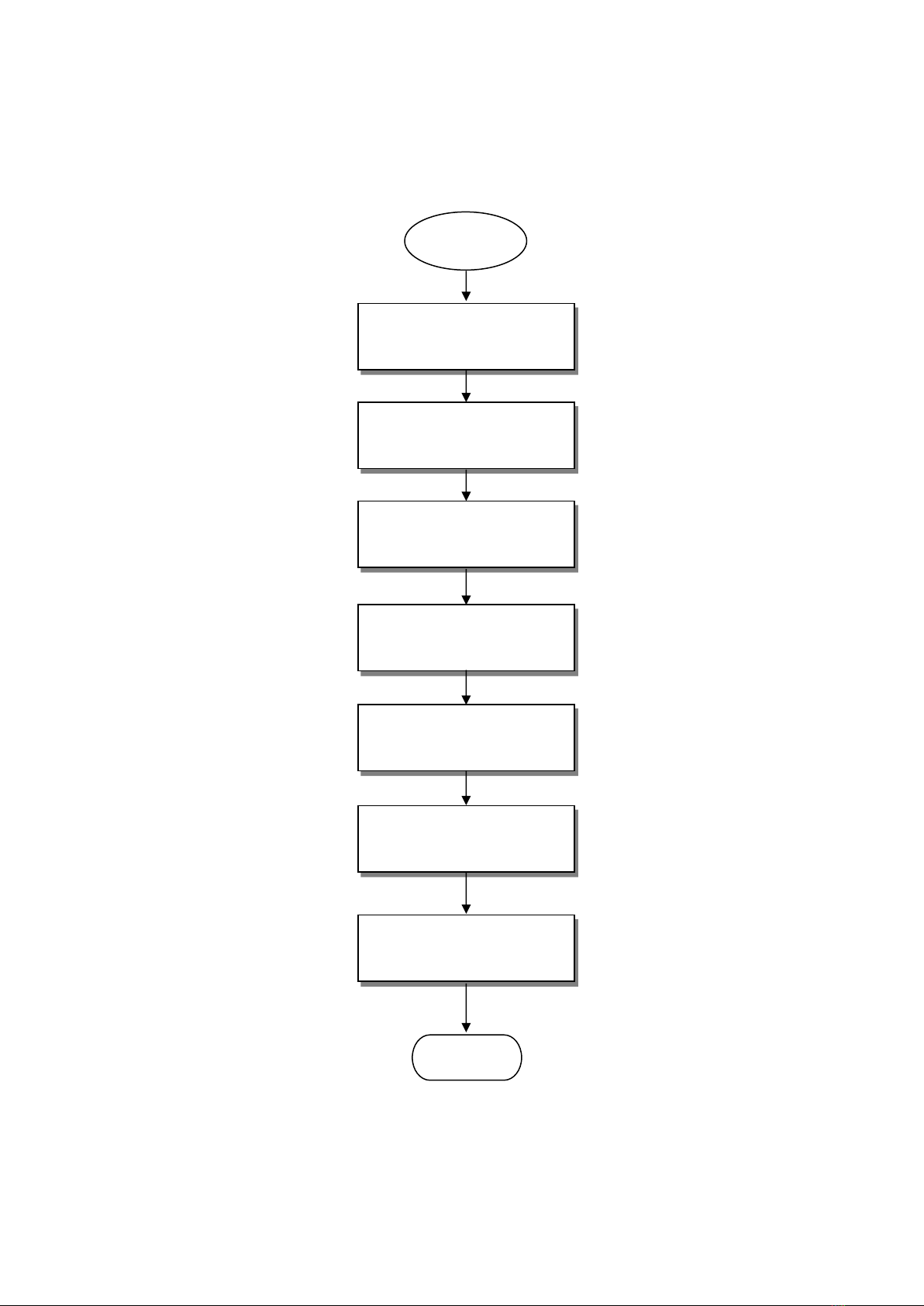
Start
Machine Installation and
Wiring
7721 tester and fixture
connection
6235 corresponding settings
and test item creation
6235 tester and fixture
connection
7721 test item creation
Using fixtures to perform
component characteristics
test
Using fixtures to perform
high voltage and interlayer
short-circuit tests
End
6
2.2 How to set the hardware architecture
⚫Main Architecture of the Three-in-one Transformer
Comprehensive Tester
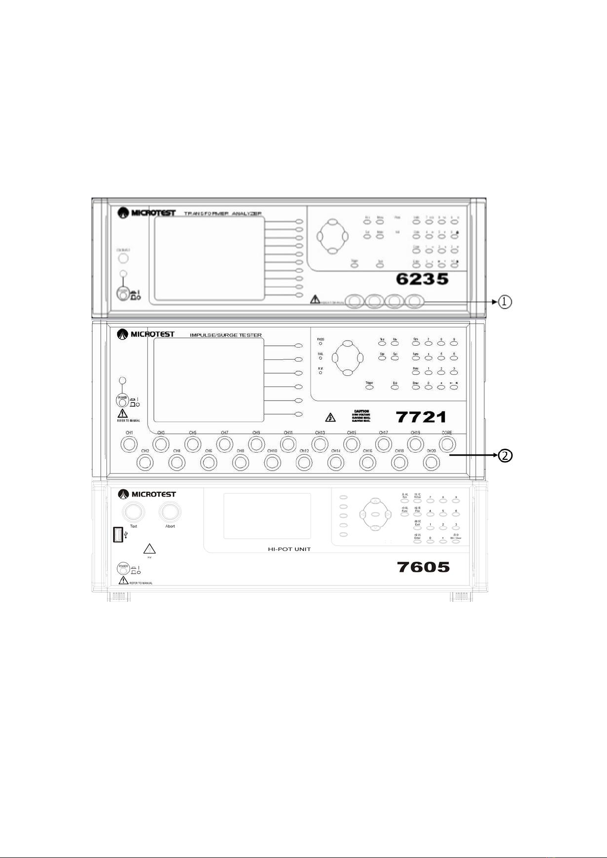
The three-in-one transformer comprehensive tester mainly consists of the three
instruments 6235, 7721 and 7605, and the F7721 high/low voltage test fixture;
the following will describe how to connect the accessories in order.
Figure 2-2-1 Full front view of the 6235, 7721 and 7605 tester
7
6235, 7721 and 7605 front wiring description: (Please refer to Figure 2-2-1)
1. This is the four-wire measuring connector of 6235; please connect the
four-wire measuring fixture connector at the end of the F7721 fixture
Test Line here.
2. 7721 high voltage output port; use the dedicated high voltage cable
from our company and connect it to the CH01~CH20 high voltage
ports of the F7721 fixture and the Core port on the fixture box
respectively using one-to-one connection. (The CH01~CH20 high
voltage ports on the F7721 fixture corresponds to the transformer slot
holes on the fixture)
⚫Full rear view of the Three-in-one Transformer
Comprehensive Tester
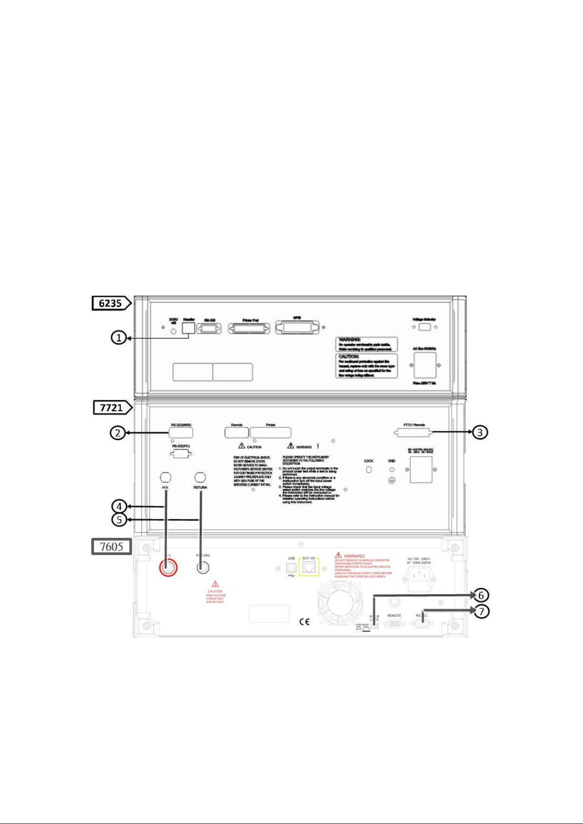
Figure 2-2-2 Full rear view of the 6235, 7721 and 7605 tester

8
6235, 7721 and 7605 rear wiring description: (Please refer to Figure 2-2-2)
1. Handle: 6235 control cable port; please use the included RJ-45 cable
from our company and connect this port to the Remote Control port
on the F7721 fixture.
2. RS-232: 7721 communication port; please connect the RS-232 cable
included from our company to this port, and connect the other end to
the RS-232 communication port of 7605.
3. Remote: 7721 control cable port; please connect the dedicated cable
included from our company from this port to the Remote port on the
F7721 fixture.
4. H.V.: 7721 high voltage input port and 7605 high voltage output port;
please use the dedicated high voltage cable to connect these two so
that high voltage can be output from CH1~CH20 on the front panel of
7721 during the withstand voltage test and insulation test.
5. RETURN: 7721 high voltage return port and 7605 high voltage
return output port; please use the dedicated high voltage cable to
connect these two so that high voltage can be returned from
CH1~CH20 on the front panel of 7721 during the withstand voltage
test and insulation test.
6. INTER LOCK: High voltage output safety socket; dedicated INTER
LOCK connector must be inserted in order for 7605 to output high
voltage successfully.
7. RS-232: 7605 communication port; please connect the RS-232 cable
included from our company to this port, and connect the other end to
the RS-232 communication port of 7721.
9
Full view of the Dedicated Fixture Box for the Three-in-one
Transformer Comprehensive Tester
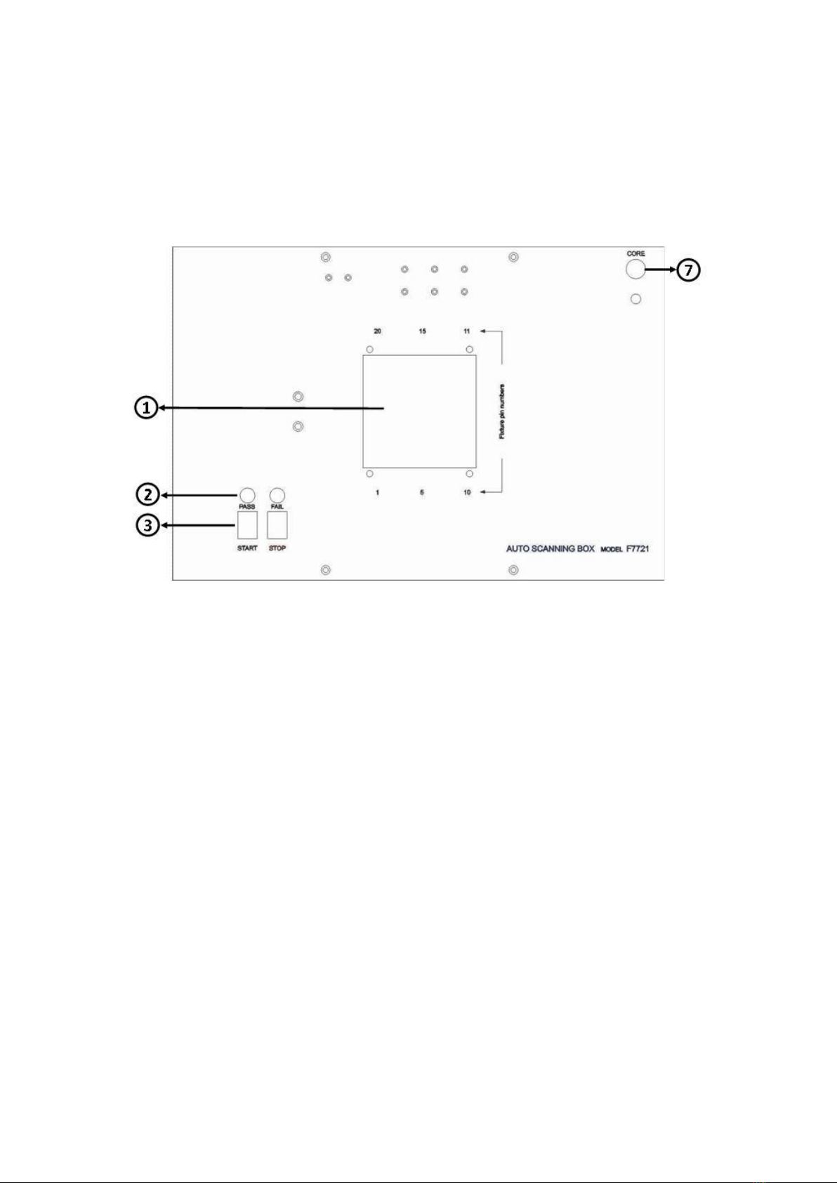
⚫F7721: Transformer fixture.
Figure 2-2-3 Top view of the F7721 transformer test fixture
Other manuals for 6235
1
This manual suits for next models
2
Table of contents
Other Microtest Test Equipment manuals

Microtest
Microtest HT-7630 User manual

Microtest
Microtest 7600 User manual

Microtest
Microtest OMNIScanner User manual

Microtest
Microtest 7630 User manual

Microtest
Microtest CT-8700 User manual

Microtest
Microtest 6235 User manual

Microtest
Microtest MICROSCANNER User manual

Microtest
Microtest CT-8750 User manual
Microtest
Microtest 6910 User manual

Microtest
Microtest MT-6920R User manual


