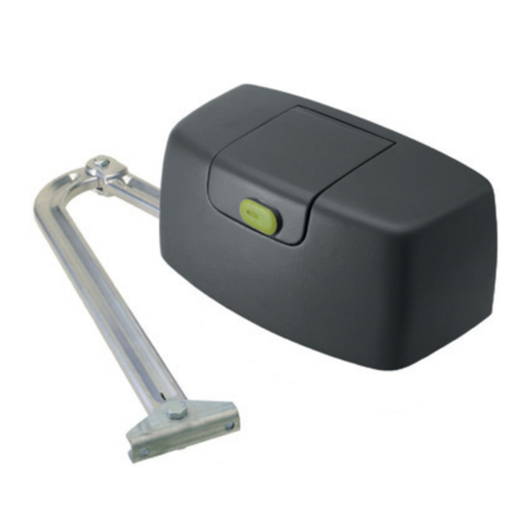
Merlin G740A User manual

1
Instructions for installation & use
Toll free helpline
Please have your serial number and
model name available before calling.
Australia 1800 638 234
New Zealand 0800 653 667
United Kingdom 0800 073 0112
www.merlingo.com
G740A
remote control openers
security at your fingertips
sliding gates
residential heavy gate opener for

G740A May 05
2
Important safety instructions for
installation
WARNING Incorrect installation can lead to severe injury. Follow all installation
instructions. Merlin Garage Openers Limited does not accept responsibility for
damage or injury resulting from installing this opener.
Prepare the gate for safe automation
Before installing the drive remove or disable any equipment, such as locks, that is not
needed for powered operation.
Check that the gate is in good mechanical condition and that it opens and closes properly.
Do not use force sensitivity adjustments to compensate for a binding or sticking gate.
Excessive force may damage the gate.
Avoid possible entrapment points
Ensure that entrapment between the driven part and the surrounding fixed parts due to the
movement of the driven part is avoided.
Gaps are considered safe as follows (IEC60335-2-103): finger gaps above 25 mm; foot
gaps above 50 mm; head gaps above 300 mm; and whole body gaps above 500 mm.
Add over-ride switch if wicket gate is present
If a wicket gate is present in a gate leaf, it must be fitted with a switch that prevents the
drive from operating when the wicket is open. (Connect a Normally Closed switch to the
STP and GND terminals of the controller board.)
Locate controls carefully
Install any fixed control, wired or wireless, within sight of the gate but away from moving
parts and at a height of more than 1.5 m.
Fit non-contact safety beams
Where they are not already explicitly required to comply with regulations, Merlin strongly
recommends fitting non-contact safety beam sensors.
Locate the entrapment warning sign correctly
After installing the drive, the included entrapment warning sign must be fitted within sight
of anyone that may stand in the path of the moving gate.
Inspect and test the installation
After installation, ensure that the mechanism is properly adjusted and that and the
protection system and manual release function correctly.
Educate the owner
Before handing controls to the user, alert them to the potential dangers, and routine checks
they’re required to perform.
Complete the commissioning check sheet
The commissioning check sheet at the end of this manual must be completed, signed
by the installer and client, and kept on record by the installing company. It contains a
declaration that all safety related procedures have been complied with.

3
Important safety instructions for
use
WARNING It is important for the safety of persons to follow all the instructions for
use. Save these instructions.
Controls are not a toy
Do not allow children to play with fixed or remote controls.
Check the gate and drive for wear
Frequently examine the installation for imbalance and signs of wear or damage.
Check that the manual release functions correctly.
Do not use if repair or adjustment is necessary.
Test the safety system every month
Every month, test that the gates stop or reverse in response to an obstruction, and that
interrupting the beam of and photo-electric safety beam also causes the gate to stop or
reverse..
Do not use if repair or adjustment is necessary.
Disconnect power before maintenance
Always disconnect the power supply from the drive before cleaning or maintaining the
gate or drive. The drive or gate may operate unexpectedly due to other users with remote
controls, or due to automatic closing (if enabled).
Become familiar with the controls and manual release before use
Before using the gate and drive, locate the manual release and become familiar with its
operation. Note where the key is located, in the case of a power cut or any failure of the
drive or gate.
Contents
Manually opening the gate 4
Maintenance 4
Learning wireless controls 5
Deleting all wireless controls 5
Deleting selected wireless controls 5
Site requirements 6
Board setup 9
Connections 9
Learn a remote control 12
Set the limits of travel 12
Template for G740A foundation plate 14
Easy setup 17
Controls 18
Professional setup 21
Testing the gate operation 22
Warranty 23
Troubleshooting 24
Specifications 25
Service Centres 26
Quick setup guide 27
Commissioning check sheet 28

G740A May 05
4
Manually opening the gate
Insert the key provided into the lever on the side of the base of the drive. Turn the key and
pull the lever outwards until it stops.
Maintenance
In an area where ant or insect infestation is likely, regularly spray around the opener and
any electrical installation with insecticide. In normal conditions it is not expected that any
additional lubrication or service is required. Keep the path of the gate free from debris and
foliage.
The gate and its moving parts may sustain damage or wear, presenting additional load to
the opener. Frequently examine the installation for signs of wear or damage. Do not use if
repair or adjustment is needed as the gate may cause injury.
Each month check the sensitivity of your gate while it is closing and opening. Arrange
for an Authorised Installer to adjust if necessary since an incorrect adjustment may be
hazardous.
Each month check that any non-contact beam sensors function correctly by obstructing
them while the gate is moving. The gate should stop, or reverse. Ensure the beams are
clear of any obstructions or dirt and ensure they are aligned towards each other.

5
Learning wireless controls
1. Press P2/RADIO until the red LED is lit.
2. If the wireless remote controls are required to only operate Pedestrian Access
mode, install the CH-RADIO jumper over its pins. If the wireless remote controls
are for full access, remove the CH-RADIO jumper.
3. Press the desired button for 3 seconds once on each wireless control that is
required to operate the gate.
NOTE The red LED will blink during learning. The controller is ready for another
wireless control when the red LED is steadily lit.
4. Press P2/RADIO to exit learning mode.
NOTE The learning procedure will time out after 10 seconds of no activity.
Deleting all wireless controls
1. Press and hold the P2/RADIO button until the red LED blinks rapidly.
2. Release the P2/RADIO button.
3. Within 6 seconds, press the P2/RADIO button again to confirm.
Deletion is indicated by the red LED blinking faster.
Deleting selected wireless
controls
The optional accessory GT/SYSTEM hand-held controller is required. Contact Merlin for
details.

G740A May 05
6
Site requirements
Check that the temperature range marked on the drive is suitable for the location. Do not
install the drive where ambient temperatures will exceed the ratings.
Gate
This opener is designed for residential
sliding gates of any length, but
weighing less than 800 kg.
Using a spring balance, check that
less than 15 kg force (150 N) is
required to manually move the gate
through its full range of movement,
with the gate disconnected from the
drive.
The gate should operate smoothly,
opening and closing without sticking.
Check the mounting points for
strength and stiffness. Reinforce if
necessary.
Gate posts
There should not be any visible flexing of the mounting points under load.
Level and square the gate
For best performance the gate track should be perfectly level along its full length. However,
for some gate weights, it will be possible to pull the gate up a slight angle. Refer to the
brochures for details, but for a 6 degree slope, the heaviest allowable gate is 300 kg; for a
3 degree slope, the heaviest allowable gate is 500 kg. The gate and its tracks and rollers
should not be damaged or bent.
Power supply
The 3-pin mains power plug should be shielded from the effects of weather.
The product is tested as a unit for electrical safety compliance and if the plug is cut off
for hard-wiring, then the electrical safety of the unit becomes the responsibility of the
installing electrician.
An isolating switch is recommended, but all mains wiring should be in accordance with
local regulations.
max 15 kg force

7
Wiring
All wiring must be arranged to prevent water entering the controller enclosure.
Do not wire mains voltages and low voltage control wires in the same conduit.
1 Opener
2 Receiving IR sensor (4-wire)
3 Transmitting IR sensor (2-wire)
4 Push-button (must be rated suitably for the weather conditions)
5 Keyed switch (must be rated suitably for the weather conditions)
6 Keypad (Merlin M840, wireless, optionally with wired power supply)
NOTE The Merlin M122 wired and M128 wireless pushbuttons are not waterproof, and
are only rated for interior use. The Merlin KWF1 keyed switch is not intended for use fully
exposed to weather in gate installations. Merlin does not warranty any items used outside
their published ratings or intended use.
Installation
Locating the foundation plate relative to the gate
Position the foundation plate correct distance from the face of the gate
Position the foundation plate as shown. Secure it using concrete and anchor bolts.
Ensure the cable conduit aligns with one of the apertures in the plate.
The surface of the foundation plate must be level and its edge must be exactly parallel to
the gate. The edge of the plate should be 50 mm from the face of the gate.
Position the foundation plate correct distance from the ends of the gate
The foundation plate must be positioned to allow the gate to move fully past the opening.
If the supplied limit actuating plates are attached to the rack with no modification then the
gate must extend past the foundation plate as per the measurements shown.
4
5
2 1
6
230-240 V ac
50/60 Hz 100W max
3

G740A May 05
8
Position the drive on the foundation plate
Remove the cover from the drive and
place it on the foundation plate.
Centre the mounting bolts in the drive’s
mounting slots.
Fit 2-mm thick spacer shims under the
drive – these will be removed aftereards.
Tighten the four bolts ensuring that the
drive is parallel to the gate
Operate the manual release clutch, using
the key provided, pulling the lever fully out.
Fix the rack
to the gate
With the clutch
released, slide the
rack over the pinion
gear. Attach one end
of the rack to the
gate, then slide the
gate along, attaching
each point of the
rack as it passes the
pinion.
Ensure sufficient rack
protrudes past the
sprocket so that the limit actuators are able to be attached.
Remove the shims
Loosen the bolts holding the drive on the foundation plate; remove the 2-mm shims.
Retighten the four mounting bolts. This provides the correct engagement of the rack and
pinion teeth.
Fit and adjust the limit actuator plates
Allow the gate to slide manually to each end position and fit the limit actuator plates to
the rack, such that the limit switch is activated. This can be fine tuned after the power is
connected to the drive.
1 2
3 4
5 6
plate must
be level
gate and foundation
plate must be parallel
50
gate
ground
50
111
50
133 min
0 min
gate
gate

9
Board setup
It is strongly recommended to follow the procedures in the order below:
1. Make all Connections
2. Learn a remote control
4. Set the limits of travel
5. Run Easy Setup
6. Adjust Controls
7. Run Professional or Easy Setup again
8. Learn wireless remote controls
Connections
NOTE When powering any accessories from the board, (for example: gate latches,
additional receivers, keypads, PE beams) ensure the total combined load on the VA and
TXF terminals does not exceed 150 mA. If necessary, remove accessories or provide
additional power supplies directly to each accessory.
230-240 V ac neutral in
230-240 V ac phase in
not connected
flashing light out
flashing light out
motor phase out (opening)
motor neutral out (common)
motor phase out (closing)
accessories power out
ground
tx photocell power out
ground
photocells in (NC)
safety device opening in (NC)
start signal in (NO)
ground
stop signal in (NC)
pedestrian access in (NO)
opening limit switch in (NO)
ground
closing limit switch in (NO)
ground
antenna in
primary windingsecondary winding
P1/SET
D
CH-RADIO
TEST
GND
ANT FCL FOP PED STP STR EDG PHO TXF U24V W V EXT L N
LAMP
8A
LAMP
GT/SYSTEM
SET
+FOR- +PAU- +OBS-
500mA
SW PW
ERR RADIO
P2/RADIO

G740A May 05
10
230-240 V ac mains input (L, N)
Connect the neutral wire to N; connect the live wire to L. An earth terminal is not
provided.
flashing warning lamp output (LAMP)
The outputs are set up for a 24 V dc, 2 W flashing warning light. The board supplies power
to the lamp, but it is a continuous supply, so the lamp must have a flashing circuit built in.
The output supplies power to the lamp from 1 second prior to opening, until fully open; and
from two seconds prior to closing, until fully closed.
motor outputs (U, V, W)
W is the neutral wire connection, and should connect to the central tapping wire of the ac
motor.
U & V are switched phase connections, and should connect either side of the motor
capacitor, and on to each motor winding wire. Ensure that U and V are connected to
give the correct closing and opening directions on the gate installation. Reverse these
connections if the motor travels in the wrong direction.
tx photocell power output (TXF), photocell signal input
(PHO)
Photocells should have NC (normally closed) contacts when there is no obstruction. Fit a
jumper wire between the signal input terminal and ground if no photocells are fitted.
The maximum total accessory power load allowed is 24 V 150 mA. The combined
consumption on the TXF and 24V terminals must not exceed this limit. Photocells are part
of this total load.
NOTE 1 If the TEST jumper is fitted, the unit performs a function test on the photocells
before each operation. This adds a 200ms delay before every operation. The transmitting
photocell must be powered from the TXF output. Photocells must have NO (normally open)
contacts when the power is off.
NOTE 2 If the PAU trimmer is set to fully anticlockwise and the photocell beam has been
interrupted, then the gate will close 1 second after the beam is cleared.
NOTE 3 The default behaviour of the gate is to react immediately when the beam is
interrupted. Professional setup Step 12 allows this to be changed. The gate can be made to
stop in response to an obstruction, and then only react after the obstruction is removed.
accessory power output (24V)
The maximum total accessory power load allowed is 24 V 150 mA.
Accessories in excess of this limit must be powered directly from an auxiliary power
supply.
NOTE Transmitting photocell must be powered from the TXF output if the TEST jumper
is fitted.
Table of contents
Other Merlin Gate Opener manuals

Merlin
Merlin Slide 600 User manual

Merlin
Merlin MGL400-24 User manual

Merlin
Merlin G703 User manual

Merlin
Merlin G930 User manual

Merlin
Merlin G950 User manual

Merlin
Merlin G715D User manual

Merlin
Merlin G915D User manual

Merlin
Merlin WingMate 3 User manual

Merlin
Merlin prolift 430R User manual

Merlin
Merlin G815D User manual

Merlin
Merlin G703 User manual

Merlin
Merlin G940 User manual

Merlin
Merlin G950 User manual

Merlin
Merlin Swing A 200 User manual

Merlin
Merlin G900 User manual

Merlin
Merlin Swing L 300 MGLSK User manual

Merlin
Merlin Swing A 200 User manual

Merlin
Merlin Swing L300 User manual

Merlin
Merlin Swing L 300 MGL Series User manual

Merlin
Merlin G950 User manual