MECNOSUD IM 5-8 Instruction Manual

IMPASTATRICE A SPIRALE SERIE IM
MANUALE DUSO E MANUTENZIONE
SPIRAL MIXER
MODEL IM
Operating manual
GB
SPIRALTEIGKNETMASCHINE
MODELL IM
Bedienungsanleitung
D
PÉTRIN À SPIRALE
MODÈLE IM
Manuel dutilisati n
F

SUMMARY
CHAPTER 1 GENERAL INFORMATION................................................................................ 24
CHAPTER 2 INSTALLATION................................................................................................. 31
CHAPTER 3 FUNCTIONING.................................................................................................. 33
CHAPTER 4 USAGE ............................................................................................................. 36
CHAPTER 5 MAINTENANCE ............................................................................................... 39
CHAPTER 6 DEMOLITION OF THE MACHINE...................................................................... 41
CHAPTER 7 AFTER SALE SERVICE ...................................................................................... 42
23
ENGLISH
Prefix
This man al is specifically for the installation, se and maintenance of spiral mixers. So yo are able to se the prod ct
in the best way. It is important that the man al is kept in good condition and sho ld stay with the machine at alltimes,
incl ding sale to another person, for sec rity in the se of the machine.
The man fact rer is not nder any obligation to notify of any f rther modification of the prod ct.
All rights of this doc ment are reserved and no alternation or reprod ctions can be made witho t permission of the
man fact rer.
The following symbols are incl ted to better stress some passages:
WARNING:
indi ates hazards that may ause serious damages; attention is required.
INFORMATION:
indi ates parti ularly important te hni al information.

24
SPIRAL MIXER - IM SERIES Operating manual
CHAPTER 1 GENERAL INFORMATION
1.1 Warranty
Guaranteed for 2 ears from date of purchase. The date must be stamped on the guarantee on
the date of purchase. Parts of the machine found to be a production defect exept electrical
components or parts worn out, will be changed and serviced free b us in our firm but onl ex our
factor within this period. Deliver expences and costs of labour are excluded from the warrant .
The warrant will not be valid when the damage is due to: transportation, mistaken or insufficient
maintenance, unskilled operators, damaging, repairs made b unauthorized personnel, non-
observance of the instructions of the manual.
All reimbursements from the manufacturer are excluded for direct or indirect damages caused in
the time the machine is inactive for the following reasons: breakdown, waiting to be repaired, or
an wa the nonpresence of the machine.
1.2 Characteristics of the machine
The mixers in the models with fixed top and bowl or with raising top and removable bowl were
made with the intention for food usage onl , to mix doughs made b cereal flours, for the prevalent
use in: pizza-restaurant, bread and baker shops.
Ever mixer (PICT. 1) is composed of:
· A steel structure protected b a heat resistant varnish.
· The bowl, the spiral, the central doughbreaker and the protection grate are all in stainless steel.
· Chain drive with oilbath gearmotor.
· The moving parts are on ball bearing.
· T pe feet (from models IM 5 and IM 8), set of wheels (for models from IM 12 to IM 44), t pe feet
in stainless steel and wheels in n lon (for IM 60)
· Operation with single-phase or threephase motor, one speed; on request: threephase motor with
two speeds and timer (apart from models IM 5 and IM 8).
· Electric circuit fed b a cable to the network to which are connected at low tension (24V) the
control devices to start, to stop, and of the safet devices. Among these l'internal blocking of the
moving parts activated b the movement of the mobile protection of the pan.
ENGLISH

25
ENGLISH
PICT. 1
IM 5; IM 8
B
AC
IM 12; IM 18; IM 25; IM 38; IM 44
B
AC
IM 12A; IM 18A; IM 25A;
IM 38A; IM 44A
AC
B

26
SPIRAL MIXER - IM SERIES Operating manual
1.3 Technical characteristics
ENGLISH
LIFTABLE HEAD AND EXTRACTIBLE STEEL BOWL
g g Lt w A C B g
FIXED HEAD AND FIXED STEEL BOWL
mm
IM 5M
IM 5T
IM 8M
IM 8T
IM 12M
IM 12T
IM 12D
IM 18M
IM 18T
IM 18D
IM 25M
IM 25T
IM 25D
IM 38M
IM 38T
IM 38D
IM 44M
IM 44T
IM 44D
IM 60M
IM 60T
IM 60D
IM 12AM
IM 12AT
IM 12AD
IM 18AM
IM 18AT
IM 18AD
IM 25AM
IM 25AT
IM 25AD
IM 38AM
IM 38AT
IM 38AD
IM 44AM
IM 44AT
IM 44AD
5
5
8
8
12
12
12
18
18
18
25
25
25
38
38
38
44
44
44
60
60
60
12
12
12
18
18
18
25
25
25
38
38
38
44
44
44
3
3
5
5
8
8
8
12
12
12
17
17
17
25
25
25
30
30
30
40
40
40
8
8
8
12
12
12
17
17
17
25
25
25
30
30
30
7
7
10
10
15
15
15
20
20
20
33
33
33
40
40
40
50
50
50
75
75
75
15
15
15
20
20
20
33
33
33
40
40
40
50
50
50
0,37
0,37
0,37
0,37
0,9
0,75
0,6/0,8
0,9
0,75
0,6/0,8
1,1
1,1
1/1,4
1,5
1,5
1,5/2,2
1,5
1,5
1,5/2,2
2,6
2,6
2,6/3,4
0,9
0,75
0,6/0,8
0,9
0,75
0,6/0,8
1,1
1,1
1/1,4
1,5
1,5
1,5/2,2
1,5
1,5
1,5/2,2
230/50
400/50/3
230/50
400/50/3
230/50
400/50/3
400/50/3
230/50
400/50/3
400/50/3
230/50
400/50/3
400/50/3
230/50
400/50/3
400/50/3
230/50
400/50/3
400/50/3
230/50
400/50/3
400/50/3
230/50
400/50/3
400/50/3
230/50
400/50/3
400/50/3
230/50
400/50/3
400/50/3
230/50
400/50/3
400/50/3
230/50
400/50/3
400/50/3
540 x 260 x 527
540 x 260 x 527
550 x 280 x 555
550 x 280 x 555
675 x 350 x 690
675 x 350 x 690
675 x 350 x 690
697 x 390 x 690
697 x 390 x 690
697 x 390 x 690
762 x 430 x 770
762 x 430 x 770
762 x 430 x 770
818 x 480 x 770
818 x 480 x 770
818 x 480 x 770
842 x 530 x 770
842 x 530 x 770
842 x 530 x 770
1020 x 575 x 1010
1020 x 575 x 1010
1020 x 575 x 1010
690 x 350 x 690
690 x 350 x 690
690 x 350 x 690
715 x 390 x 690
715 x 390 x 690
715 x 390 x 690
780 x 430 x 770
780 x 430 x 770
780 x 430 x 770
838 x 480 x 770
838 x 480 x 770
838 x 480 x 770
878 x 530 x 770
878 x 530 x 770
878 x 530 x 770
33
33
36
36
60
60
60
65
65
65
95
95
95
105
105
105
110
110
110
250
250
250
80
80
80
85
85
85
115
115
115
130
130
130
140
140
140
237 x 160
237 x 160
260 x 200
260 x 200
317 x 210
317 x 210
317 x 210
360 x 210
360 x 210
360 x 210
400 x 260
400 x 260
400 x 260
452 x 260
452 x 260
452 x 260
500 x 270
500 x 270
500 x 270
550 x 370
550 x 370
550 x 370
317 x 210
317 x 210
317 x 210
360 x 210
360 x 210
360 x 210
400 x 260
400 x 260
400 x 260
452 x 260
452 x 260
452 x 260
500 x 270
500 x 270
500 x 270
M= Monophase Motor T= Threephase Motor D= Threephase Motor 2 speeds
Model neading capacity Flour capacity Bowl volume Motor power Volt Dimensions mm WeightBowl dimension

1.4 Electrical schemes
27
ENGLISH
SINGLE-PHASE CONNECTION IM 5- M
TM
N
L
F500mA
F
TM
2,5VA
START
RL1
1
M
RP1 RP2
+
-
B
Led
C
MC1
START
RL1 RP1 RP2
+
-
1
M
UV
L
1
L
2
LINE
GND
BRL2
STOP
CLED
RP1
RP2
F500mA
RL2
STOP
R2
MC2
SINGLE-PHASE CONNECTION IM 12-1 -25-3 -44 M
L
N
Q15
L2 L3
LINE
123
T1618M
1-
1-
PE
F500mA
M15
1
MC
T
14 9
PT
8 7 10 11
F17
START-
12
13
PE
N
L
Q15
1
M15
18M
L
N
1
3 2
230V
F500mA
F17
T16
8VA
24V
(14)
(13)
PT
(12)
(11)
T
MC (10)
(7)
STOP
START
(8)
13
14
18M
(9)
A1
A2
18M

28
SPIRAL MIXER - IM SERIES Operating manual
ENGLISH
THREE-PHASE CONNECTION IM 12-18-25-38-44-60 T
PE
L1
A2
K18M
A1
(9)
K18M
14
1
(1 )
(11)
(12)
(10)
(7)
(8)
START
STOP
MC
T
PT
(14)
F500mA
F17
MC
24V
8VA
T16
2 0V/400V
2
1
K18M
L1
PE
Q15
M15
K18M T16
1
12
START-
F17
111078
PT
914
T
M15
F500mA
1-
1- 21
LINE
LL2
Q15
L2
L
L1
L2
L L
L2
L1
THREE-PHASE CONNECTION 2 VEL. IM 12-18-25-38-44-60 D
2 0V/40
L1
L2
LL
L2
L1
L1
L1
L2
L
PE
LINE
Q15
L2 L 12
1-
1-
F500mA
M15
T
14 9
PT
8 7 10 11
F17
START-
12
1
T16K18M
Q15
PE
K18M
1
2
T16
8VA
24V
MC
F17
F500mA
(14)
PT
T
MC
STOP
START
(8)
(7)
(10)
(12)
(11)
(1 )
1
14
K18M
(9)
A1
K18M
A2
COMM
M15
COMM
29
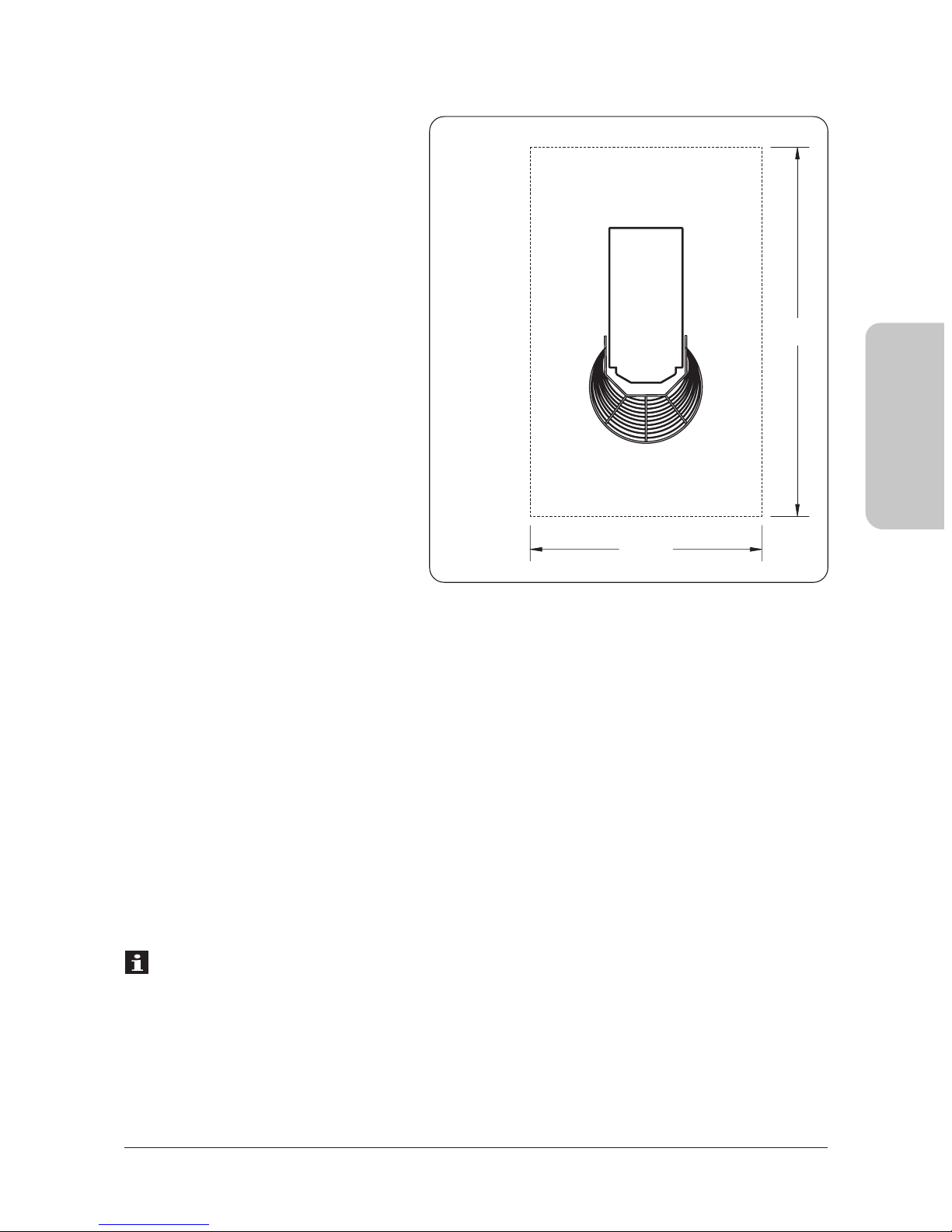
1.5 Operating area
In normal working conditions and to have the best exploration of the potentiality of the machine,
the operator needs the area represented in PICT. 2.
1.6 Security indications
Altho gh the machine is b ilt in conformity to the req ired sec rity r les regarding electrical,
mechanical and hygienic reg lation it can be dangero s if:
· Used in case and condition different to those described by the man fact rer.
· Manomission of the protection and of the safety devices.
· Innattention to the instr ction of: Installation - F nctioning - Usage - Maintenence.
INFORMATIONS
Insta ation and maintenence have to be done by qua ified personne authorized by the
manufacturer who is not responsab e for any mistaken insta ation or manomission.
ENGLISH
E ectrica schemes
SINGLE-PHASE
AND THREE-PHASE CONNECTION
IG = General switch
T16 = Transformer
F17 = F se
PT = Thermoproction of the engine
FC = Safety photocell
MC = Safety limit switch
STOP = Stop b tton
START = Operating b tton
K18M = Contactor
LI = Operating light
M = Engine
PICT. 2
mt 1,5
mt 2

30
SPIRAL MIXER - IM SERIES Operating manual
ENGLISH
1.7 Security indications
INFORMATION
Carefully read the instruction efore using the machine.
WARNING
The avoid dangerous condition and/or possi le injuries caused from: electric current, mechanical
parts, fire or hygienical pro lems, you must follow the security indications step y step.
A) Keep in order your working area. Disorder can cause dangerous accidents.
B) Consider environmental conditions. Do not use the machine in humid, wet or nadly
lit environments, close to inflama le liquids or gas.
C) Keep away from children and non authorized personnel. Do not permit them to go
near the machine or the working area.
D) Only utilize the machine with the correct voltage. Normal usage gives etter results.
E) Dress in adequate way. Do not wear hanging clothes or any items which can e caught
in the machine. Use non-slip shoes. For hygiene and safety keep your hair tied ack and
wear protective gloves.
F) Protect the ca le. Do not pull the ca le to extract the plug. Do not leave the ca le
near high temperatures, sharp o jects, water or solvents.
G) Avoid insecure positions. Find the est surface to ensure the machine is alanced.
F) Always pay maximum attention. Do not e distracted when using the machine.
I) Take the plug out. When the machine is not in use, efore cleaning, maintenance
and moving it.
L) Do not use further extensions.
M) Check that the machine is not damaged. Before using the machine carefully check
that all security devices are working. Check that: the mo ile parts are not locked,
there are not any parts damaged, all the parts have een set up correctly and all the
conditions that could influence the regular functioning of the machine
are in working order.
N) Repairing the machine y qualified personnel. The repairs can only e done y qualified
people, using original spare parts. The non- compliance with these rules can represent
danger for the user.

31
2.1 Instructions for the user
The environmental conditions in which the machine must be installed must follow these characteristics:
· Be dry
· The machine is constructed to have IPXI protection level.
· Water and heat sources at safe distance
· Adequate ventilation and li htin correspondin to hy iene and security re ulations followin
the existin laws.The surface should be flat and compact for easier cleanin . For normal ventilation
of the machine no objects should obstruct.
INFORMATION
The electric network must be pro ided with an automatic differential switch ha ing characte
ristics suitable to those of the machine, in which the opening distance between the contacts
must be of at least 3 mm. Most of all it is necessary a good grould system.
WARNING
Verify that the electrical set-up corresponds with the numbers of the technical characteristics
(1.3) found and on the small plate at the back of the machine.
2.2 Installation methods
The machine is supplied in a closed packa e and fixed with metal straps on wood. Inside the
packa in with the machine you will find the instructions and the declaration of conformity
accordin to the machines re ulation. The machine must be unloaded and lifted out at the part
indicated on the packa in by proper equipment. For the transportation of the machine to the
place of installation, use a fork lift.
After cuttin the metal straps take out of the packa in and the plastic cover, then with the help
of a proper belt put under the machine (PICT. 3) and a fork lift (manual or motor) lift the machine
and take away the bottom pallet, position the machine makin sure you leave a space around it
of 50 cm to make usa e, cleanin and maintenance easier. If the machine is unstable put under
the feet or wheels pieces of hard rubber. If the machine has wheels make sure they have been
blocked by pushin the lever A downwards till it blocks (PICT. 4).
Note: All packa in must be disposed of in a lawful way.
CHAPTER 2 INSTALLATION
ENGLISH
This manual suits for next models
2
Other MECNOSUD Mixer manuals


