Makita TW0200 Manual

Continuous Rating (W)
Voltage (V) Cycle (Hz) Input Output Max. Output(W)
110
120
220
230
240
Models No.
Description
PRODUCT
Current (A)
TECHNICAL INFORMATION
CONCEPT AND MAIN APPLICATIONS
Specification
Standard equipment
Optional accessories
< Note > The standard equipment for the tool shown may differ from country to country.
P 1 / 11
Dimensions : mm ( " )
Width ( W )
Height ( H )
Length ( L )
50 / 60
50 / 60
50 / 60
50 / 60
50 / 60
251 (9-7/8)
72 (2-13/16)
220 (8-5/8)
L
H
W
The advanced version of the existing model 6904VH has been
released with the following features.
* Aluminum hammer case with high durability
* Compact body size ; 251mm (9-7/8")
* Ergonomical palm fitting soft grip
TW0200
Impact Wrench
380
380
380
380
380
160
160
160
160
160
300
300
300
300
300
3.6
3.3
1.8
1.7
1.7
200 (150)
2.5 (8.2)
2.0 (6.6) for Australia
2.1 (4.6)
12.7 (1/2)
0 - 2,200
0 - 2,200
Max. fastening torque : N.m (ft.lbs)
Net weight: kg (lbs)
No load speed (min-1=rpm)
Impact per minute (min-1=ipm)
Square drive : mm ( " )
Capacities
Power supply cord : m ( ft )
High Tensile bolt
Standard bolt M10 - M16 (3/8" - 5/8" )
M10 - M12 (3/8" - 1/2" )
* Socket 17-38
* Socket 17-52
* Socket 19-38
* Socket 19-52
* Socket 19-78
* Socket 21-38
* Socket 21-52
* Socket 21-78
* Socket 21-150
* Socket 22-38
* Socket 22-52
* Socket 23-38
* Socket 23-52
* Socket 24-45
* Socket 24-52
* Socket 26-50
* Socket 26-78
* Extension bar
* Universal joint
* Bit adaptor
* Socket 17-38 .................................... 1 pc.
* Socket 19-52 .................................... 1 pc.
* Socket 21-38 .................................... 1 pc.
* Plastic carrying case ........................ 1 pc.

Repair P 2 / 11
< 1 > Lubrication
Apply MAKITA grease N. No.1 to the following portions marked with black triangle to protect
parts and product from unusual abrasion.
2
2
7
9
13
13
14 17
20
20
Hammer
Compression
spring 32
Cup
washer 19
Position No. Descriptions
Hammer case
Flat washer 32
7
9
Anvil
Internal gear 71
17 Spindle
31 pcs. of
Steel balls 3.5
2 pcs. of
Steel balls 6.4
Cylindric portion where
7 anvil reciprocates.
Amount : g (oz)The portion to be lubricated
Approx. 0.1 (0.01)
Approx. 0.5 (0.02)
Approx. 0.5 (0.02)
Approx. 0.5 (0.02)
Approx. 0.5 (0.02)
in total
Approx. 2.0 (0.07)
in total
* The hole portion where 17 spindle
contacts.
* The portion where hammer
contacts.
* The groove portion where 13 steel
balls 6.4 move.
* The hole portion where armature
gear is inserted.
10
10
2 cps. of Spur
gears 32
14
* The side where 9 steel balls 3.5
contact.
Teeth portion

Repair P 3 / 11
< 2 > Removing armature
< 3 > Disassembling mechanical section
( 1 ) After removing brush holder cap and carbon brushes, remove bumper with a slotted head screwdriver. See Fig. 1.
( 2 ) Unscrew 4 pcs. of hex socket head bolts M5x50 together with urethane rings and cup washers each 4 pcs.
Then, hammer case section can be removed from motor housing together with armature. See Fig. 2.
( 3 ) Do not separate internal gear cover from hammer case, because the grease leaks out, or inner parts can fall off
the hammer case. Then, holding hammer case together with internal gear cover, pull off the armature
as illustrated in Fig. 3.
Fig. 1 Fig. 2
Fig. 3
Fig. 4
Bumper Carbon brush
Brush holder cap
Carbon brush
Brush holder cap Hammer case
Internal gear cover
Armature
Hammer case
section
Cup washers 5
Urethane rings 5
Hex socket head bolts M5x50 5
Motor housing
Internal gear cover
Hammer case
Armature
( 1 ) Separate internal gear cover from hammer case. Take off the following parts from hammer case. See Fig. 4.
* Internal gear 71
* O ring 58
* Flat washer 19
* Anvil
* Hammer section
Flat washer 19
Anvil
Hammer section
Internal gear 71
O ring 58 Internal gear cover
Anvil
Hammer case O ring 12
Remove O ring 12 from internal gear case.
<Note >
* Flat washer 19 can remain in hammer case.
* Inner parts can be removed from hammer case
by hand. However, if it is difficult to remove by
hand, strike anvil with plastic hammer. See Fig. 4A. Fig. 4A

Repair P 4 / 11
< 4 > Assembling mechanical section
< 5 > Disassembling hammer section
Fig. 5
Fig. 6
Fig. 7
Fig. 8
1. Mount O ring 58 to internal gear cover. Aligning the tabs of internal gear with the accepting holes of
internal gear cover, mount internal gear 71 to internal gear cover. See Fig. 5.
Before assembling, apply MAKITA grease N. No.1 with referring to "< 1 > Lubrication" at page 2.
2. Mount hammer section with engaging spur gears 32 with internal gear 71. see Fig. 6.
1. Remove flat washer 18 and 2 pcs. of pin 6 from spindle. Then, 2 pcs. of spur gear 32 can be removed. See Fig. 8.
3. Mount flat washer 19 and anvil to hammer case. And mount hammer section, internal gear 71 and internal
gear cover to hammer case. Mount O ring 12 to internal gear cover. See Fig. 7.
Internal gear 71
Align these Tabs with the
accepting holes of internal
gear cover.
Internal gear cover
O ring 58
Internal gear cover
Internal gear cover
Hammer section
Hammer section
Spur gears 32 Internal gear 71
Internal gear 71
Flat washer 19 : This part can remain
in hammer case, when
disassembling the mechanical
section.
Hammer case
Anvil
O ring 12
Spur gear 32
Spur gear 32
Spindle
Hammer
Flat washer 18
Pin 6 Pin 6

Repair P 5 / 11
Fig. 9
Fig. 10
Fig. 11
Fig. 11A
2. Pull hammer toward spur 32 side with "No.1R045 Gear extractor", and in order to take out steel ball 6.4
align the top of cam groove of spindle with the opening portion of hammer. See Fig. 9.
3. Loosen the handle of "No.1R045 Gear extractor" slowly until the spindle is free from the compression spring 32.
See Fig. 10. Then, the hammer section can be disassembled as illustrated in Fig. 11.And then, 31 pcs.of steel ball 3.5
and flat washer 21 can be removed from hammer as illustrated in Fig. 11A.
The top of cam groove
and
The opening portion of hammer
Steel ball 6.4
No.1R045
Gear extractor
Spindle
Spindle
Hammer
Hammer
Cup washer 19
Compression
spring 32
31 pcs. of steel ball 3.5
and flat washer 21 remain
in hammer in this stage.
31 pcs. of steel
balls 5.5
Flat washer 21
Fig. F
< Note >
Do not hold the hammer section as illustrated in Fig. F.
Because, steel balls 3.5 fall off the hammer, when separating spindle
from hammer.

Repair P 6 /11
< 6 > Assembling hammer section
Fig. 13
Fig. 12
Fig. 14 Fig. 15
Spindle
Cup washer 19
Compression
spring 32
Hammer
Steel ball 6.4
No.1R045
Gear extractor
Flat washer 32
31 pcs. of
steel balls 3.5
1. Put 31 pcs. of steel ball 3.5 and flat washer 32 into hammer. See Fig. 12
After mounting compression spring 32, cup washer 19 and spindle to hammer, press the hammer toward the spur
gear installing side with "No.1R045 gear extractor" . See Fig. 13.
2. Align the top of cam groove of spindle with the opening portion of hammer. And then, mount 2 pcs. of
steel ball 6.4 to spindle. See Fig. 14. Mount spur gears 32, pins 6 and flat washer 18 to spindle. See Fig. 15.
3. Mount the assembled hammer section to the machine with referring to "< 4 > Assembling mechanical
section" at page 4.
Spur gear 32
Spur gear 32
Spindle
Hammer
Flat washer 18
Pin 6 Pin 6
The top of cam groove
and
The opening portion of hammer

Repair P 7 / 11
< 7 > Removing baffle plate
1. Slide baffle plate to the overhang portion of handle cover. And remove it by pulling in the direction of
black arrow.
< 8 > Removing handle cover and F/R change lever
Fig. 17
Fig. 18
Fig. 16
Baffle plate
Handle cover
Baffle plate
Handle cover
F/R Change lever
F/R Change lever
Overhang portion
of handle cover
1. After removing hook, unscrew 3 pcs. of tapping screw 4x18, and disengage switch from F/R change lever.
See Fig. 17.
2. Push F/R change lever in the direction of the arrow 1. Pull the lever in the direction of 2, and then, pull out in the
direction of 3. So, F/R change lever can be removed from handle cover. See Fig. 18.
Tapping screws
4x18
Hook
1
2
3
F/R change lever
Handle cover
Switch

Repair P 8 /11
Fig. 19
2
1
3
< 9 > Mounting handle cover and F/R change lever
Fig. 21
Handle cover
F/R Change lever
Tapping screws
4x18
Hook
1. Push F/R change lever in the direction of the arrow 1. Push the lever in the direction of 2, and then, push in the
direction of 3. So, F/R change lever can be mounted to handle cover. See Fig. 19.
2. Engaging the tab of switch with the groove
of F/R change lever, mount switch to
handle cover. See Fig. 20.
3. Mount handle cover to motor housing and fasten it with 3 pcs. of tapping screw 4x18. Mount hook.
See Fig. 21.
< Note >
Face the marking about material
to the mechanical section side
( up side) as per the illustration,
so the groove for engaging with switch
faces automatically to switch, and
possible to mount F/R change lever
to handle cover and engage it with
switch.
The groove for engaging with switch is carved
another side of this portion
Marking about material
Tab of switch
Fig. 20
F/R Change lever

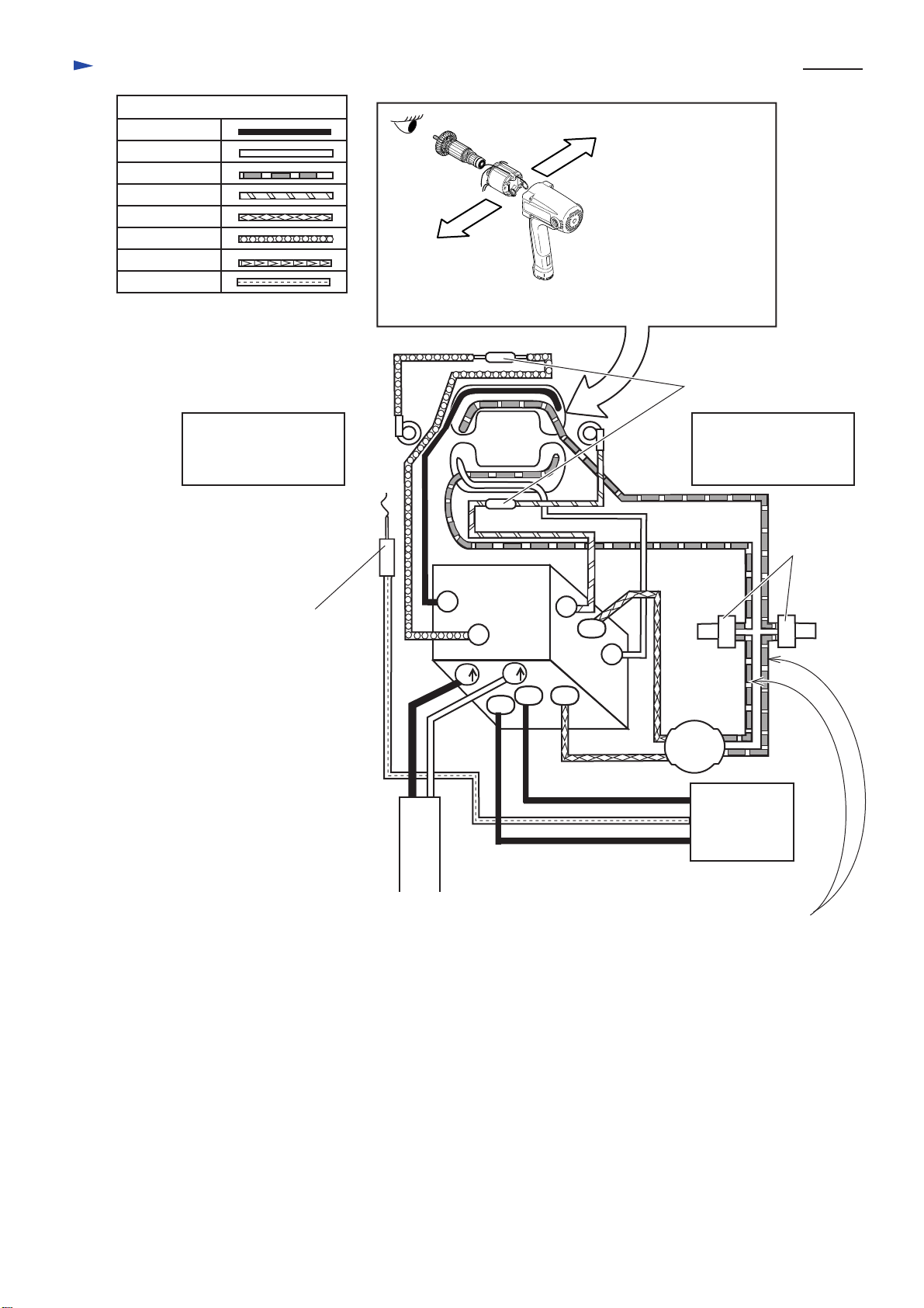
Circuit diagram without Line Coil P 9 / 11
Color index of lead wires
Black
White
Red
Orange
Blue
Brown
See-through
Purple
2
3
M1
C1 C2
12
Field
Switch
Noise
Suppressor
Power Supply
Cord
Connect this grounding
terminal with field core.
The following illustration of
field shows the view from
armature fan side.
4
1
M2
Choke coils
clamped on field
< Note >
* Choke coils are not used for all countries.
* Noise suppressor is not used for all countries.
* Noise suppressor of two lead wire type is used for some countries in stead of
three lead wire type.
Right
viewing from
armature fan side
Left
viewing from
armature fan side
Left
(viewing from
armature fan side)
Right
(viewing from
armature fan side)
The following illustration of
field shows the view from
armature fan side.
Left
(viewing from
armature fan side)
Right
(viewing from
armature fan side)
Circuit diagram with Line Coil P 10 /11
Color index of lead wires
Black
White
Red
Orange
Blue
Brown
See-through
Purple
2
3
M1
C1 C2
1
Field
Switch
Insulated
Terminals
Noise
Suppressor
Power Supply
Cord
Connect this grounding
terminal with field core. 4
Choke coils
clamped on field
Right
viewing from
armature fan side
Left
viewing from
armature fan side
Line
Coil
1
M2
2
White lead wires can be used for
connecting insulated terminals
to line coil.
Other manuals for TW0200
14
Table of contents
Other Makita Impact Driver manuals

Makita
Makita TW0350 User manual

Makita
Makita TW0350 User manual

Makita
Makita 6935FDWDE User manual

Makita
Makita TD0101 User manual

Makita
Makita TW1000 Quick start guide

Makita
Makita 6910 Quick start guide

Makita
Makita TD090D User manual

Makita
Makita BTL060 User manual

Makita
Makita DTD134 User manual

Makita
Makita TW0350 User manual

Makita
Makita TD0101 User manual

Makita
Makita DTWA260 User manual

Makita
Makita BTD140 Quick start guide

Makita
Makita 6951 User manual

Makita
Makita BTD133 User manual

Makita
Makita XT706 User manual

Makita
Makita TL064DSAE User manual

Makita
Makita DTD171 User manual

Makita
Makita 6905B User manual

Makita
Makita BTD132 User manual