Page 1
REV. 2-C-050818
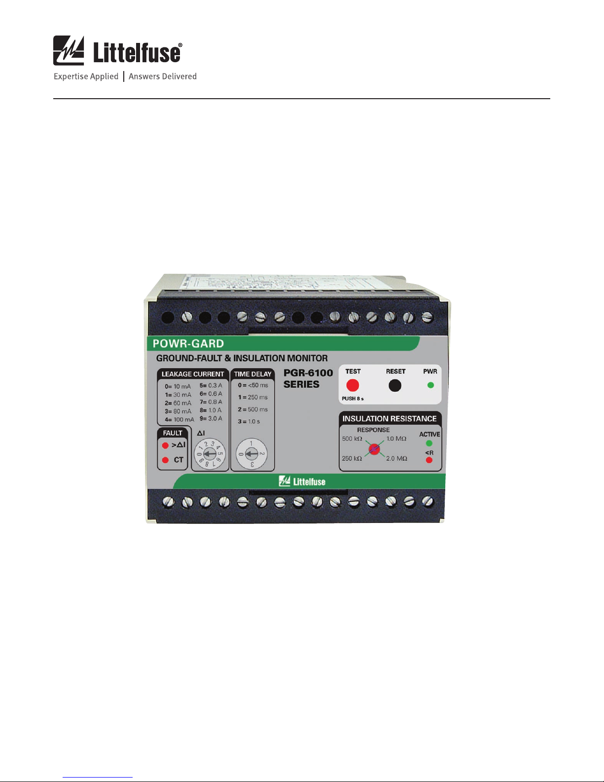
PGR-6100 Ground-Fault & Insulation Monitor
1. GENERAL
The PGR-6100 Ground-Fault & Insulation Monitor can
detect a motor ground fault whether the motor is running
(Online mode) or stopped (Offline mode). The PGR-6100 can
also be used to protect a motor that is supplied by a solidly
grounded, resistance-grounded or ungrounded system. For
ungrounded systems, use only the Offline mode.
Grounded systems use a current transformer (CT) to detect
ground-fault currents as low as 10 mA when the motor is
running. Insulation resistance is measured to detect a fault
when the motor is stopped. Online or Offline mode is selected
with a digital input connected to a starter auxiliary contact.
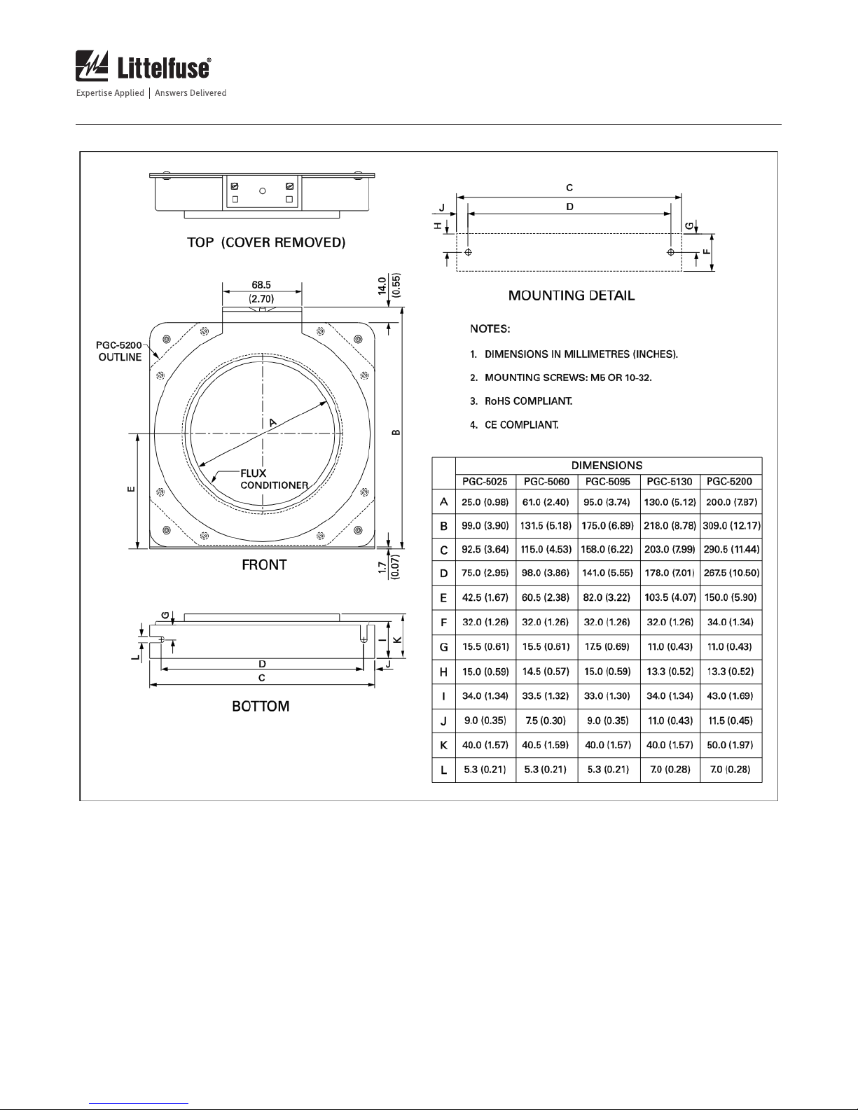
In the Online mode, ground-fault current is sensed by
a PGC-5000-series zero-sequence CT. The trip level of the
ground-fault circuit is selectable from 10 mA to 3 A. Trip
time is selectable from <50 ms to 1.0 s. Additional current-
detection features include harmonic filtering, a relay output
that can operate in the fail-safe or non-fail-safe mode, CT-
connection detection, LED trip, LED power and LED open-CT
indication, autoreset or latching trips with front-panel and
remote reset, a test button, and a 0-to-1-mA analog output.
In the Offline mode, insulation-resistance monitoring is
enabled with a selectable 250-k to 2-M alarm-setting
range. Additional insulation-monitoring features include
a relay output that can operate in the fail-safe or non-fail-
safe mode, LED active and low-resistance indication, and a
0-to-1-mA analog output.
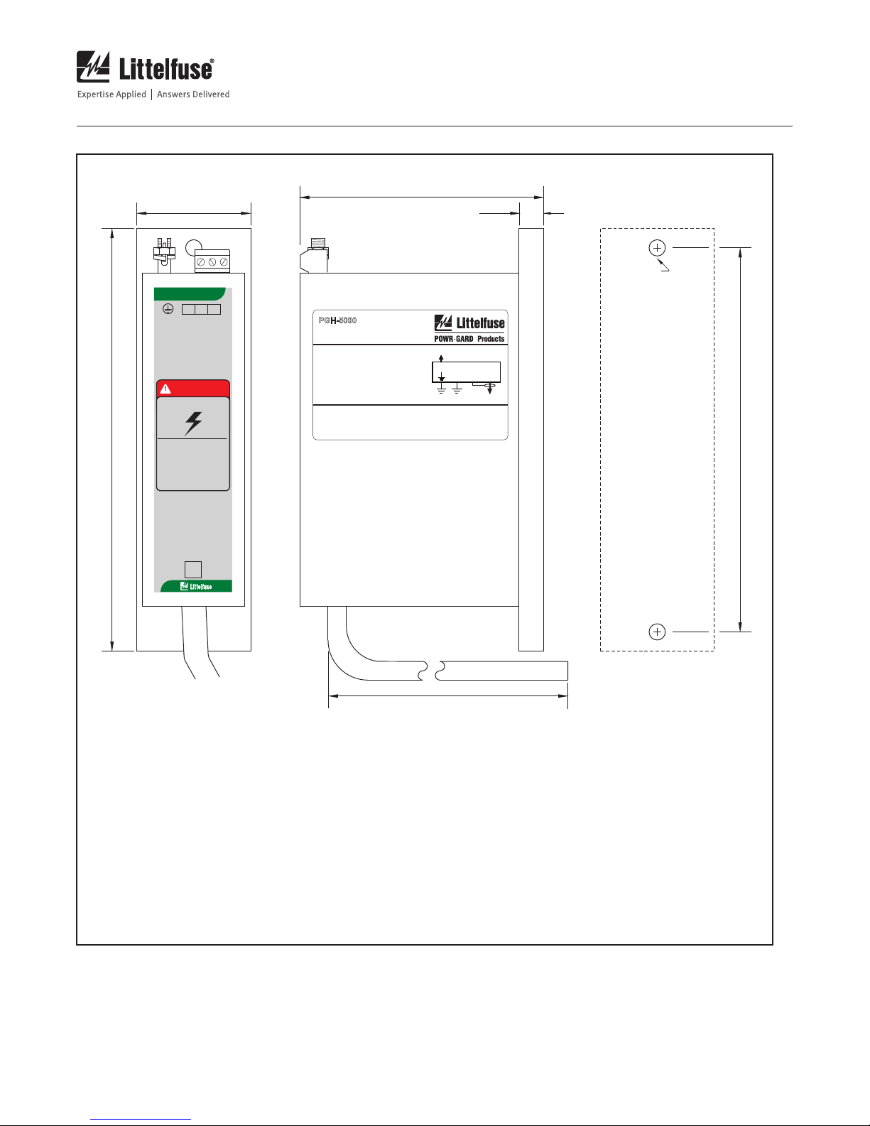
The PGR-6100 can be directly connected to a supply up to
1.3 kV. For systems from 1.3 to 5 kV, use a PGH-5000 High
Tension Coupler. For systems from 5 kV to 6 kV, use a PGH-
6000 High Tension Coupler.
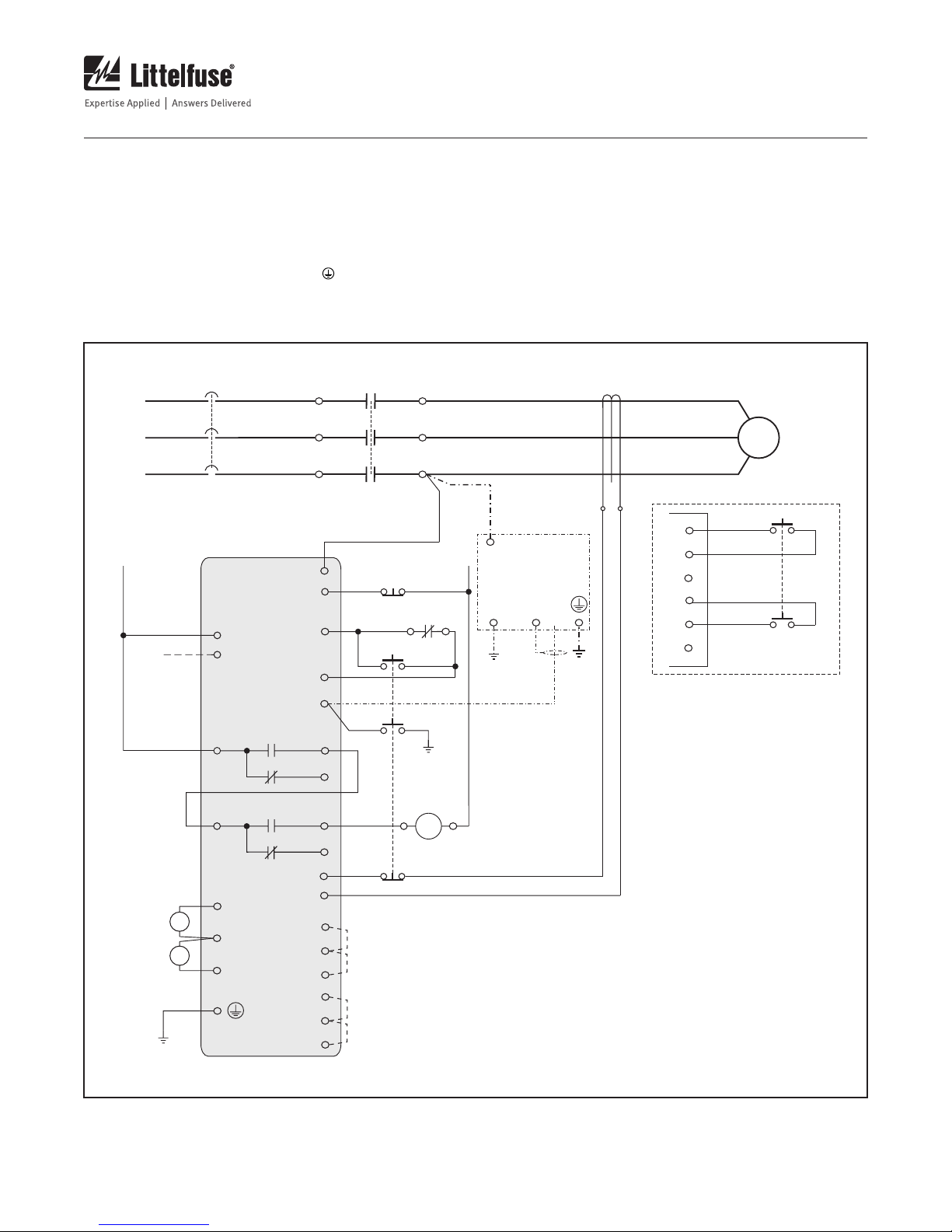
2. OPERATION
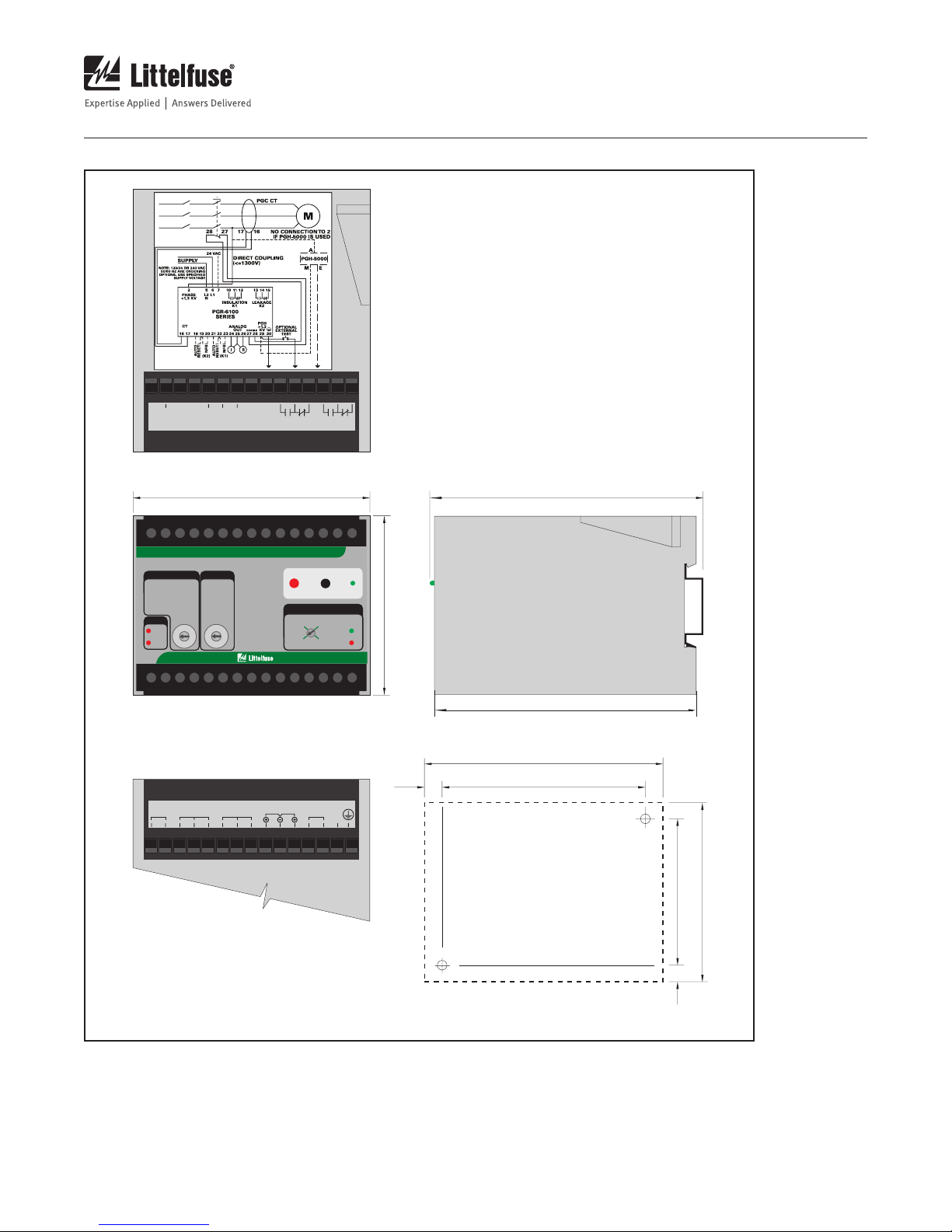
2.1 Output Relay Operating Mode
In the fail-safe mode the output relays energize when power
is applied and the ground-fault and insulation-resistance
circuits are not tripped. Fail-safe mode is the factory setting.
For a non-fail-safe operation, connect terminals 19-20 and
22-23. The respective output relay will energize when a fault
occurs. See Fig. 2.
2.2 PGR-6100 Operating Mode
Connect terminals 27 and 28 to a normally closed (Form B)
auxiliary starter contact. When terminals 27 and 28 are open,
Online mode is selected (insulation monitoring off). When
terminals 27 and 28 are connected, Offline mode is selected
(insulation monitoring active).
2.2.1 Online Operation
In Online mode, the PGR-6100 in conjunction with a
PGC-5000-series zero-sequence current sensor operates
as a ground-fault relay.
2.2.2 Ofine Operation
The PGR-6100 changes mode by means of an auxiliary
contact on the main contactor when the motor is off. It
becomes an insulation-resistance monitor and imposes a
small dc voltage to the motor windings and supply cable from
the motor starter. Leakage to ground is detected.
2.3 Front-Panel Controls
2.3.1 Ground-Fault Trip Level
The Leakage Current ∆Iselector switch is used to set the
ground-fault trip level from 10 mA to 3 A. For ground-fault
detection, the switch setting must be set substantially below
the prospective ground-fault current. To avoid sympathetic
tripping, the switch setting must be above the charging
current of the protected feeder.
2.3.2 Ground-Fault Trip Time
The PGR-6100 has a definite-time trip characteristic. In
tripping systems, the TIME DELAY selector is used to set the
ground-fault trip time for coordination with upstream and
downstream ground-fault devices. Trip time is selectable
from < 50 ms to 1.0 s. Coordination requires the same trip
level for all ground-fault devices in a system and the trip
time to progressively increase upstream. The amount of
equipment removed from the system will be a minimum if the
first ground-fault device to operate is the one immediately
upstream from the fault.
2.3.3 Insulation Resistance Response
The PGR-6100 insulation resistance function has an
adjustable alarm range of 250 k to 2 M . There is no
selectable time delay. The unit will operate in less than three
seconds.
2.3.4 Reset
The front-panel RESET button is used to reset latching trips.
After a fault has been cleared, cycling the supply voltage will
also reset the PGR-6100.
To use the PGR-6100 in autoreset mode, connect terminals
18-19 and 21-22. See Fig. 2.
Press the RESET button for several seconds. The reset
function is not instantaneous.