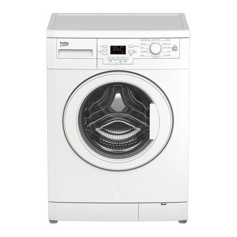
LG WT-R10(~3)3(7)1(3 User manual

WASHING MACHINE
SERVICE MANUAL
MODELS : WT-R10(~3)3(7)1(3,5)TP(H)
WT-R80(5)1
WT-Y1(~4)K
WT-R852, WT-R902
CAUTION
Before servicing the washer, Read the safety precautions in the manual.

2
SAFETY PRECAUTION!
DISASSEMBLE POWER CORD BEFORE SERVING
RECONNECT ALL GROUNDING DEVICES
IMPORTANT SAFETY NOTICE !
This service information is intended for individuals
possessing adequate backgrounds of electrical,
electronic and mechanical experience.
Any attempt to repair this appliance may result in
personal injury or property damage.
The manufacturer or seller can not be responsible
for the interpretation of this information, nor can it
assume any liability in connection with its use.
CONTENTS
1. Specifications ..................................................................................................................................................3
2. Installation Instructions....................................................................................................................................4
3. Operating Instructions
3-1. Identification of Parts...........................................................................................................................10
3-2. Before Starting to Wash ......................................................................................................................11
3-3. Function of Each Button......................................................................................................................16
3-4. Washing Programs..............................................................................................................................18
3-5. Other Functions...................................................................................................................................20
3-6. Care and Maintenance........................................................................................................................23
4. Service Information
4-1. Schematic Diagram.............................................................................................................................24
4-2. Wiring Diagram ...................................................................................................................................25
4-3. Program Time Chart............................................................................................................................26
4-4. Disassembly Instruction ......................................................................................................................29
4-5. Test Running without water.................................................................................................................34
4-6. Trouble Shooting Methods against Common Washing Problems.......................................................35
4-7. Trouble Shooting Methods According to Error Message ....................................................................36
4-8. How to Diagnose and Repair by Symptom.........................................................................................38
5. Exploded View ............................................................................................................................................47
6. Replacement Part List...................................................................................................................................51

3
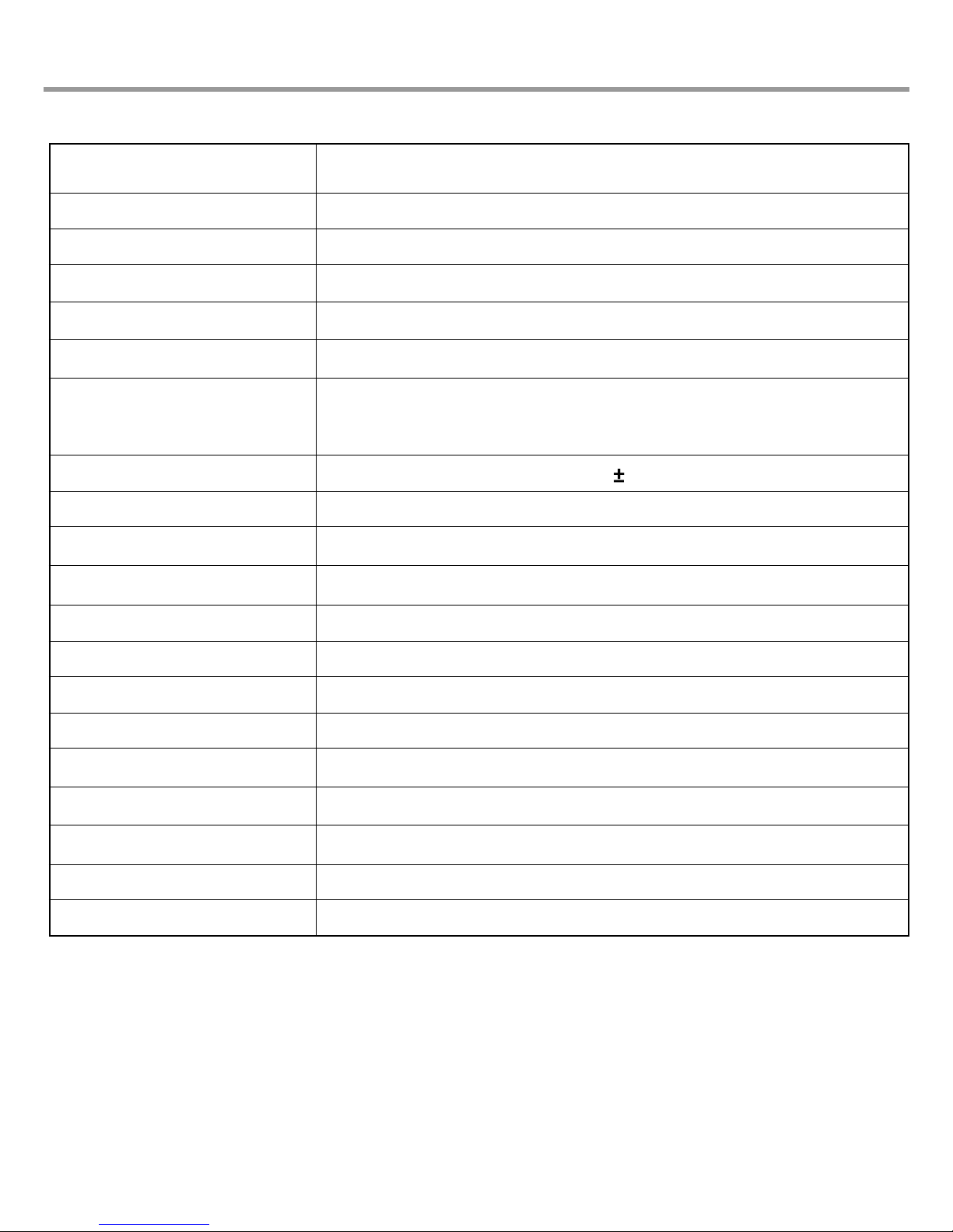
1. SPECIFICATIONS
WT-R10(~3)3(7)1(3,5) Series / WT-R80(5)1/ WT-Y1(~4)K/WT-R852/WT-R902
Refer to rating label on the back of Washer
Stainless
0.3kgf/cm2~ 8kgf/cm2
250V, 8A for 220~240V/50Hz
125V, 12A for100~127V/60Hz
710 50
Refer to rating label on the back of Washer
DELICATE, WOOL, NORMAL, SPEEDY, JEAN
7 Stages
Available for 3 ~ 24 Hr
Magnet Sensor
Applied
Double
Applied
Applied
Applied
Applied
Model
Power Sourse
Input
Capacity
Inner Tub
Inlet Water Pressure
Rating of Fuse
Spin Speed
Dim.
Weight
Program
Water Level
Reservation
Lid Interlock Switch
Child Lock
Lint Filter
Softener Dispenser
Detergent Dispenser
Bleach Inlet
Auto Power Off

2. INSTALLATION INSTRUCTIONS
4
2-1. HOW TO INSTALL THE WASHING MACHINE
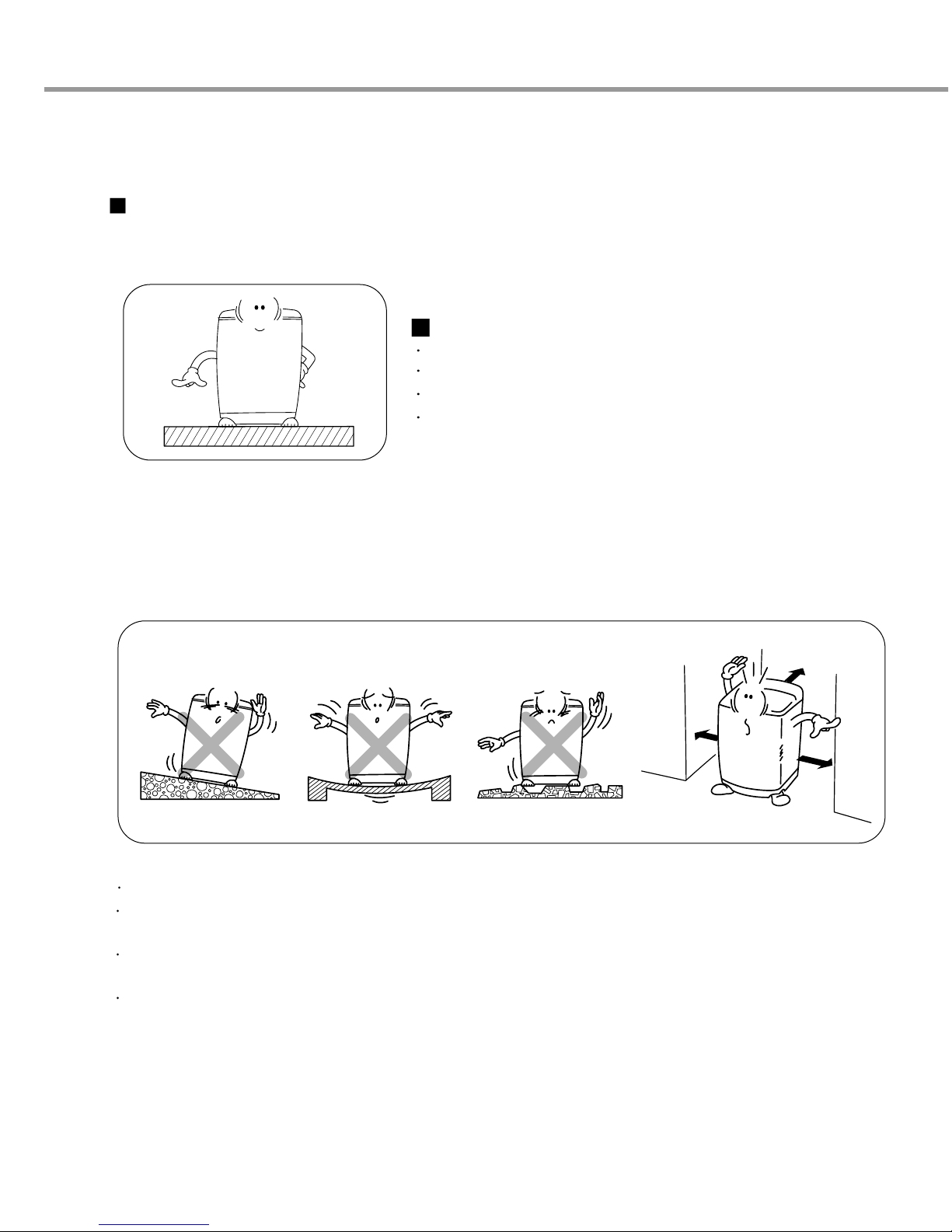
Selection of the installing place
Install the washer on the horizontal solid floor.
If the washer is installed on an unsuitable floor,it could make considerable noise and vibration.
Do not install the washer in the following places
Where the washer is exposed to direct sunlight.
Near a heater or heating appliance.
Where the washer is exposed to freezing temperatures.
In damp environments such as bathrooms or harmful
environments such as near a coal gas source.
The proper installation of the washing machine can increase the wash effectiveness and the life of it.
If the washer is installed on an inclined floor, it could make considerable noises and vibration
and could cause a malfunction.
Use the adjustable leg spindle to adjust the level of washing so that it sits properly.
Install the washing machine on a level and firm surface.
Keep the washing machine more than 10cm from the wall to prevent vibration noise
during spinning
The base opening must not be obstructed by carpeting when the washing machine is
installed on a carpeted floor.
Wooden floors may need reinforcing to prevent the normal vibration which occurs with an
unbalanced load.
10cm
10cm
10cm

5
2-1. HOW TO LEVEL THE WASHING MACHINE
Check the level of the washing machine using a spirit level on the side of the washer cabinet
You can check the level also by visually lining up the washer with the fills, adjacent walls or cabinets.
You can level the washer using the adjustable leg spindle fitted to the cabinet.
Screw the ADJUSTABLE LEG SPINDLE legs up or down as required.
When washing machine does not even out, turn ADJUSTABLE LEG SPINDLE right or left to be level.
Location of drop
Cause How to adjust
Adjust the front adjusting plate with the adjustable
legs(2) or adjust the adjustable legs.
Adjust the rear adjusting plate with the adjustable
legs(2) or adjust the supporting plate.
Adjust the left part of the front and rear adjusting
plates or the supporting plate.
Adjust the right part of the front and rear adjusting
plates or the supporting plate.
When the front is lower.
When the rear is lower.
When the left is lower.
When the right is lower.

6
2-2. CONNECTING WATER SUPPLY HOSE
Before connecting Water Supply Hose to water tap, check your hose type
and choose correct instruction. Water Supply Hose may vary according to
the country.
Make sure connect blue inlet hose to cold water tab, and orange inlet hose
to hot water tab.
Connecting Water Supply Hose to water tap
Rubber packing
Water supply hose
Connector
Untighten the screw
Untighten the screw of the connector so
that the tap can be placed in the middle.
Fixing the connector to the tap
Push the upper connector up till the rubber
packing is in tight contact with the tap. Then
tighten the 4 screws.
Attach the water supply hose to the connector
Push the water supply hose vertically
upwards so that the rubber seal within the
hose can adhere completely to the tap.
Check the connection of water supply hose and the connector
After connecting the hose, open the tap to
check for any water leakage.
In case of water leakage, close the tap and
start again from step 1
Fixing the connector of connector and water supply hose
Attach the water supply hose to the
connector and then tighten it by screwing it
to the right.
Normal Type
Normal tab without thread & screw type inlet hose.)
1
2
3
4
5

7
Rubber packing
Screw
Fixed sticker
Rubber packing
Guide plate
Connector
Connector
Fixed sticker
Middle
Connector Middle
Connector
Water Supply Hose
Pressing rod Pressing handle
Connector
Middle
connector Fixed Stiicker
Pressing Handle
Pressing Rod
Water Supply Hose
Separate Middle connector from Water Supply Hose
Separate Middle connector from the Water
Supply Hose by pulling the Pressing Rod and
the Pressing Handle that is attached to the
Water Supply Hose while pressing them.
Loosen the fixed nuts to connect the connector to the tap
Untighten the screw of the connector so that
the tap can be placed in the middle.
Fixing Connectors to the Tap
Push the upper connector up till the rubber
packing is in tight contact with the tap. Then
tighten the 4 screws.
Fixing Upper Connector and Middle Connector
Remove the fixed sticker in between the
Upper and Middle Connectors. Tighten the
connectors by holding one connector and
twist middle connector to the right.
Connecting Middle Connector and Water Supply Hose
Press down the pressing rod of the Water
Supply Hose which was separated from
middle connector(refer to Step1) and then
join it to the middle connector.
One Touch Type
If the tap diameter is too large or is square,
open the 4 screw and take out the guide
plate and follow step 1.
In case the tap is large.
Note
Checking the water leakage
After connecting the hose, open the tap to
check for any water leakage.
In case of water leakage, close the tap and
start again from step 1.
If you skip step1, it may cause water leakage.
(NORMAL TAB WITHOUY THREAD & ONE TOUCH TYPE INLET HOSE.)
1
2
3
4
5
6

8
Attach the water supply hose to the tap.
Push the water supply hose up so that the
rubber packing within the hose can adhere
completely to the tap.
Connect the water supply hose to the tap.
Connect the water supply hose to the tap and
then tighten it by screwing it to the right.
Check water leakage.
After connecting the hose, open the faucet to
check for any water leakage.
Connect the water supply hose to inlet valve
of the washing machine, and then lock it by
turning the hose connecting part.
Check to see if there is a rubber seal inside
the connector.
Screw Type
Water Supply Hose
Rubber Packing
H
Rubber seal
Water
tap
Connecting Water Supply Hose to the machine
1
2
3

9
2-3. CONNECT THE DRAIN HOSE
2-4. FLOODING DRAINAGE
For pump model
For non - pump model
Connect the drain hose to
the outlet of the drain pump
located at the rear of the
washing machine.
Attach the clip to the drain
hose. And then push it toward
the body of the washing
machine as indicated by the
arrow.
Check that the drain hose is hung
up over the edge of the laundry tub.
Do not use an extension hose.
Hose
Guide
Within 50mm
0.9~
1.2m
Drain Hose
Holder
Holes for the Holder
Push
Holes
For Holder
Never lay down the drain hose, as water will be discharged.
Be sure the drain hose is properly routed so it will not kink or lift from the sink.
The discharge height should be approximately 0.9~1.2m from the floor.
Connect the drain hose adjusting the length of it not to be dropped. If drain hose
is dropped the drainage could be poor because of blockage in the hose.
Connect the drain hose to the outlet of the
drain located at the back side of the
washing machine.
Fix the drain hose with the clip.
And then push it toward the body as in the
figure.
Keep it downward while the washing machine is working.
Ensure the hose is free from kinking.
● You machine requires a floor drainage slope (or hole) that will SAFELY DISPOSE of the FULL FLOW of any water that may leak
out should the machine malfunction.
It is therefore the OWNER'S RESPONSIBILITY to make sure this machine is installed in an area with a drain hole (or slope) that
will prevent any possibility of water damage to floor coverings or property.
●
Do not install the washer where it is directly exposed to sunlight, wind, rain, etc.
●
Plug the power cord of this washer into a properly installed standard power outlet that is grounded.
●
Your machine requires a floor drainage slope (or hole) that will SAFELY DISPOSE of the FULL FLOW of any water that may leak
out should the machine malfunction. It is therefore the OWNER’S RESPONSIBILITY to make sure this machine is installed in an
area with a drain hole (or slope) that will prevent any possibility of water damage to floor coverings or property.
●
Permissible water temperature : Max 70˚C (160˚F)
●
Permissible water pressure : Max 116psi (800 kpa, 8 kg/cm2), Min 4 psi (30 kpa, 0.3 kg/cm2)
●
If water temperature and pressure are greater than above, it may cause damage to the machine. If you have uncontrolled water
temperature and pressure you should fit a temperature and pressure relief valve to ensure that water temperature and water
pressure remain within the safe limits. Consult a plumber or electrician if you are unable to adjust water temperature and pressure.
●
Do not over tighten the coupling nuts with a tool. Inlets are plastic : Do not strip or crossthread.
CAUTION

10
3. OPERATING INSTRUCTIONS
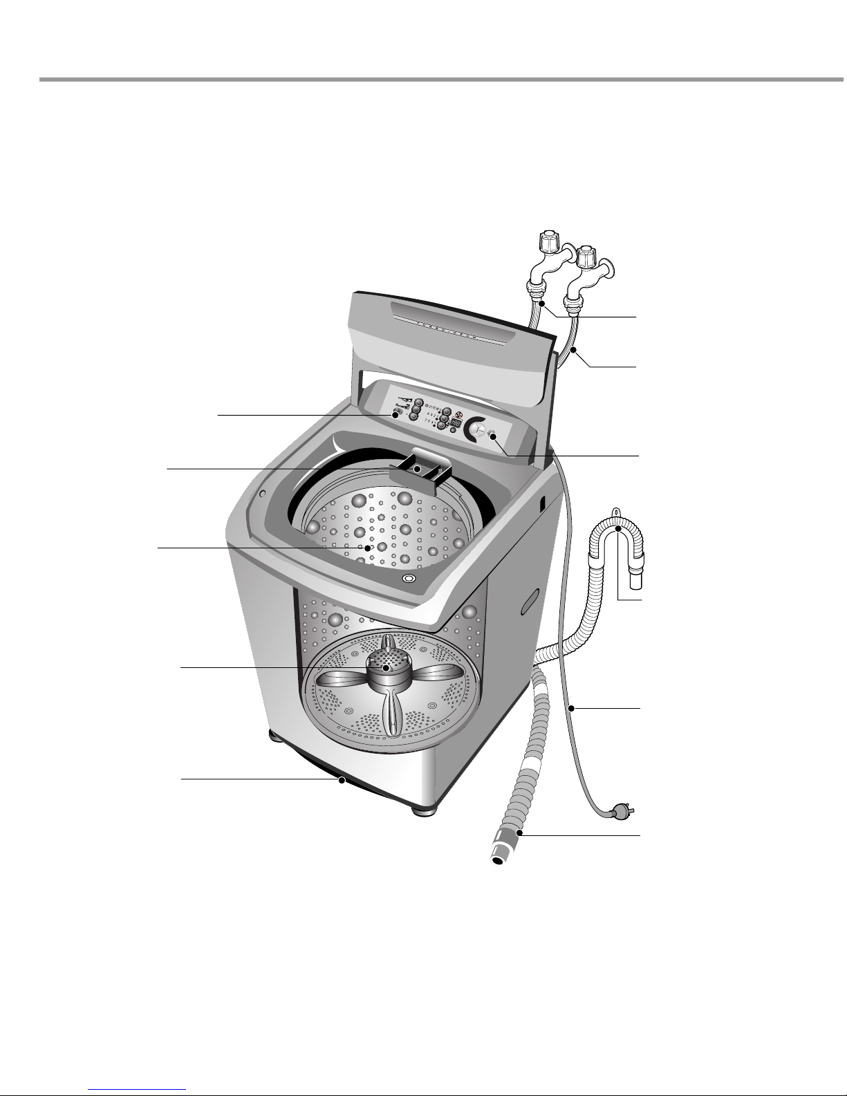
3-1. IDENTIFICATION OF PARTS
HOT WATER SUPPLY
HOSE
COLD WATER SUPPLY
HOSE
Make sure the water
does not leak.
FUNCTION SELECTOR
Powder detergent
(powder bleach)box
for delayed washing/
softener box
Washing Tub
stainless steel tub
START/PAUSE
BUTTON
Use to start or stop the
washing machine
temporarily.
Anti Rat Base
DRAIN HOSE
For non Pump Model
• Keep downward while the
washing machine is
working.
DRAIN HOSE
For Pump Model
• Check out if the drain hose
is located in the laundry tub
before operating the washing
machine.
POWER PLUG
If the supply cord is
damaged, it must be
replaced by the manufacturer
or its service agents or
a similarly qualified person
in order to avoid a hazard.
SPIN SPEED INDICATOR
SILENT
COLD
HOT
DELAY
WOOL
NORMAL
SPEEDY
PRO
GRAM
START
PAUSE
POWER
JEAN
DELICATE
NOINLET
DOOROPEN
DRAIN Er.
STAIN
LEVEL
WATER
LEVEL
WATER
TEMP
.
WASH
RINSE
MIN
MIN
MIN
SPIN
S M L XL
LIGHT HEAVY
SOAK
DELAY/TIME LEFT
Turbo clean filter
Other manuals for WT-R10(~3)3(7)1(3
1
This manual suits for next models
10
Table of contents
Other LG Washer manuals
Popular Washer manuals by other brands

Tricity Bendix
Tricity Bendix AW 1000 W Operating & installation instructions

Panasonic
Panasonic NA-F60L5WRB operating instructions

GE
GE WSLP1500 Dimensions and installation information

Electrolux
Electrolux EWF1284EDW Service manual

Bosch
Bosch WAN2829BSN User manual and installation instructions

VESTEL
VESTEL CMH-XL 7510 TE user manual