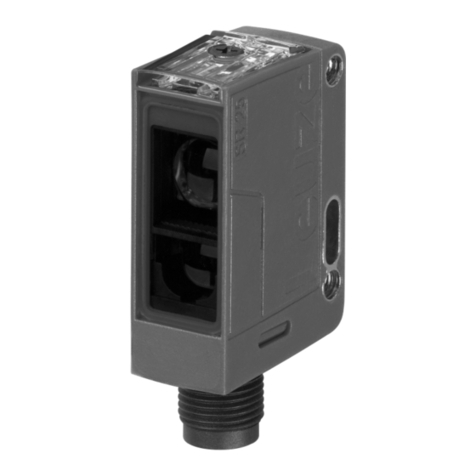
Leuze KRT18BW User manual

Leuze electronic GmbH + Co. KG In der Braike 1 D-73277 Owen Tel. +49 (0) 7021 573-0
[email protected] • www.leuze.com
We reserve the right to make changes • PAL_KRT18BW_2_en_50147926.fm
White light transmitter
Easy to adjust through display of the signal
strength on the device
Simple sensitivity adjustment with multiturn
potentiometer
Removable rotary operating knob enables
comfortable, tool-free adjustment
Maximum packing quality through short
response time
Automatic luster suppression
Remote control via control cable
Blocking of all operational controls via con-
trol cable
Accessories:
(available separately)
Mounting systems
(BTU 200M…, BT 95)
Mounting adapter for standard design (80
mm x 53 mm x 30 mm) BTX 018M
Cable with M12 connector
(K-D M12…)
Dimensioned drawing
AIndicator diodes
BKnurled knob for sensitivity adjustment (removable)
CDisplay of the special functions
DOptical axis
EHorizontal light spot orientation (transverse)
FLight spot orientation vertical (lengthwise)
GLight/dark switching toggle switch
Electrical connection
BRBR
/
BNBN
OUTOUT
2
GND
GND
OUTOUT
1
12
12
-
3030
V
+
IN
IN
WSWS
/
WHWH
BLBL
/
BUBU
SWSW/
BKBK
GRGR
/
GYGY
KRT18BW White light contrast sensor
KRT18BW. …2…
en 2022/04/08 50147926

KRT18BW. …2… 2022/04/08
Technical data
Optical data
Operating range 13mm ± 3mm
Light source 1)
1) Average life expectancy 100,000h at an ambient temperature of 25°C
White LED
Light spot dimensions 1mm x 4mm (at a distance of 13 mm)
Light spot orientation Vertical (lengthwise) or horizontal (transverse)
Time behavior
Switching frequency 15kHz
Response time 33µs
Readiness delay < 300ms
Electrical data
Operating voltage UB 2)
2) For UL applications: use is permitted exclusively in Class 2 circuits according to NEC
12 … 30VDC (incl. residual ripple)
Residual ripple ≤15 % of UB
Open-circuit current 25mA (at 24V)
Switching outputs/functions OUT1 Push-pull, PNP dark switching (dark on),
NPN light switching (light on), changeover-capable
OUT2 Push-pull, PNP light switching (light on),
NPN dark switching (dark on), changeover-capable
Signal voltage high/low ≥(UB-2V)/≤2V
Output current Max. 100mA
Input IN Configuration input and blocking of the operational controls
Indicators
Green LED continuous light Ready
Yellow LED continuous light Switching signal - dark switching (dark on)
Bar graph Reception signal strength, 13-level
Yellow LEDs - special functions Light/dark switching
Mechanical data
Housing Diecast zinc, chemically nickel-plated
Connector Diecast zinc, chemically nickel-plated
Optics PMMA
Operation Multiturn potentiometer for sensitivity adjustment,
button for changing between light/dark switching
Weight 60g
Connection type M12 connector, 5-pin
Environmental data
Ambient temp. (operation/storage) -40°C … +60°C/-40°C … +70°C
Protective circuit 3)
3) 2=polarity reversal protection, 3=short circuit protection for all transistor outputs
2, 3
VDE protection class 4)
4) Rating voltage 50V
III
Degree of protection IP67, IP 69K
Light source Exempt group (in acc. with EN 62471)
Standards applied IEC 60947-5-2
Certifications UL 508, C22.2 No.14-13 2) 5) 6) 7) 8)
5) These proximity switches shall be used with UL Listed Cable assemblies rated 30V, 0.24A min,
in the field installation, or equivalent (categories: CYJV/CYJV7 or PVVA/PVVA7)
6) For use in NFPA 79 applications only.
7) Adapters providing field wiring means are available from the manufacturer. Refer to manufacturers information.
8) Caution – Use of controls or adjustments or performance of procedures other than specified herein may result in
hazardous light exposure.
Chemical resistance Tested in accordance with ECOLAB
Additional functions
Full control of the application 13-level bar graph signal display on the device
Light/dark switching (L/D) Can be activated via control button
KRT18BW
Notes
Glossy objects:
With glossy objects, the
sensor is to be fastened at
an inclination of
approx. 10° … 15° rela-
tive to the object surface.
Alignment aid:
An alignment aid is
included in the scope of
delivery of each sensor.
This facilitates simple
alignment of the sensor to
the working distance of 13
mm without needing to
perform electrical
commissioning.
Observe intended use!
This product is not a safety
sensor and is not intended
as personnel protection.
The product may only be put
into operation by competent
persons.
Only use the product in ac-
cordance with its intended
use.

10°…15°
13 mm
13 mm

Leuze electronic GmbH + Co. KG In der Braike 1 D-73277 Owen Tel. +49 (0) 7021 573-0 KRT18BW. …2…
[email protected] • www.leuze.com
Part number code
KRT 1 8BW. H2 / G6 T - M1 2
Operating principle
KRT Contrast sensor
Series
18B 18B series
Light source
WWhite light
Light spot orientation
HHorizontal (transverse)
VVertical (lengthwise)
Setting
2Multiturn potentiometer with bar graph signal display, light/dark switching via button
Pin assignment of connector pin 4 / black cable wire (OUT1)
GPush-pull switching output, PNP dark switching (dark on), NPN light switching (light on)
Pin assignment of connector pin 2 / white cable wire (OUT2)
6Push-pull switching output, PNP light switching (light on), NPN dark switching (dark on)
Pin assignment of connector pin 5 / gray cable wire (IN)
TInput for light/dark switching and locking of the operational controls
Connection technology
M12 M12 connector, 5-pin
KRT18BW White light contrast sensor

KRT18BW. …2… 2022/04/08
Order guide
The sensors listed here are preferred types; current information at www.leuze.com
Mounting adapter BTX 018M
With the help of mounting adapter BTX 018M (part no. 50133412), contrast sensors KRT18B… can be mounted on existing mounting
devices for contrast sensors in the standard design (80mm x 53mm x 30mm).
Order code Part no. Features
KRT18BW.H2/G6T-M12 50147611 Light spot orientation horizontal (transverse), antivalent push-pull outputs, potentiometer with bar graph
Selectable additional function: light/dark switching
KRT18BW.V2/G6T-M12 50147605 Light spot orientation vertical (lengthwise), antivalent push-pull outputs, potentiometer with bar graph
Selectable additional function: light/dark switching
Accessories
BTX 018M 50133412 Mounting adapter for mounting on mounting devices for sensors in the standard design (80 mm x 53 mm x 30 mm)
KRT18BW

Leuze electronic GmbH + Co. KG In der Braike 1 D-73277 Owen Tel. +49 (0) 7021 573-0 KRT18BW. …2…
[email protected] • www.leuze.com
Adjusting the switching threshold
The sensitivity of contrast sensor KRT18B is set via the multiturn potentiometer.
Adjustment procedure
The description is provided using the example of a dark mark on a light background. For the case of a light mark on a dark background,
the terms mark and background simply need to be exchanged.
1.Positioning the background under the light spot.
If the bar graph indicator is to the left of the middle position, turn the multiturn potentiometer clockwise until the sensor switches
off (yellow indicator LED Q1 off). Several full turns may be necessary here.
2.Positioning the mark under the light spot.
If the bar graph indicator is to the right of the middle position, turn the multiturn potentiometer counterclockwise until the sensor
switches on (yellow indicator LED Q1 on). Several full turns may be necessary here.
3.Switch between mark and background and watch the bar graph while doing so. Turn the multiturn potentiometer until the deflec-
tion between the mark and the background is symmetric about the middle of the bar graph.
4.If you are not able to find a setting that enables reliable detection, repeat the process with a different detection color.
Turning the spindle clockwise increases the sensitivity of the sensor. The
signal on the bar graph is increased.
Turning the spindle counterclockwise reduces the sensitivity of the
sensor. The signal on the bar graph is reduced.
LED Q1 off:
LED Q1 on:
>12s
L
/
D
>12s
L
/
D
>12s
L
/
D
>12s
L
/
D
Q1
>12s
L
/
D
>12s
L
/
D
Q1
KRT18BW White light contrast sensor

KRT18BW. …2… 2022/04/08
Multiturn potentiometer
A removable operating button is plugged into the multiturn potentiometer at the factory. The setting of the contrast sensor can thereby be
performed manually without the need for a tool. If this is not desired, the operating button can be pulled off. A screwdriver is then needed
for the setting.
L/D – Light/dark switching
Press the C button longer than 12s. Release the button. To change the setting again, push the button
again for longer than 12 s and release.
Only the green LED flashes. 1) Only for devices without analog output

>12s
L
/
D
Rear view of sensor
with operating button plugged
If necessary, loosen then operating button
with a screwdriver
>12s
L
/
D
>12s
>12s
L
/
D
>12s
L
/
D
LED off =
OUT1 (Pin 4): PNP dark switching,
NPN light switching
OUT2 (Pin 2)1): PNP light switching,
NPN dark switching
LED on =
OUT1 (Pin 4): PNP light switching,
NPN dark switching
OUT2 (Pin 2)1): PNP dark switching,
NPN light switching
>12s
L
/
D
>12s
KRT18BW

Leuze electronic GmbH + Co. KG In der Braike 1 D-73277 Owen Tel. +49 (0) 7021 573-0 KRT18BW. …2…
[email protected] • www.leuze.com
Sensor adjustments via the IN input (Pin 5)
Signal level LOW ≤2V
Signal level HIGH ≥(UB-2V)
Light/dark switching
PNP light switching / light on, NPN dark switching / dark on (OUT1)
PNP dark switching / dark on, NPN light switching / light on (OUT1)
Locking all operational controls via the IN input (Pin 5)
A static HIGH signal (≥20ms) at the IN input (Pin 5)
locks all operational controls on the sensor if required,
such that no manual operation is possible (e.g., protec-
tion from erroneous operation or manipulation).
If the input is not connected or if a static LOW signal is
being applied, all operational controls are unlocked and
can be operated freely.
LOW
t = 420 ... 480 ms
t
HIGH
LOW
t = 520 ... 580 ms
t
HIGH
>12s
12
%
>12s
L
/
D
KRT18BW White light contrast sensor
This manual suits for next models
4
Table of contents
Other Leuze Accessories manuals

Leuze
Leuze ODS 96 M/V Mounting instructions

Leuze
Leuze HTU330 Series User manual

Leuze
Leuze DDLS 170 Parts list manual

Leuze
Leuze KRT3CM Series User manual

Leuze
Leuze IGSU 14E User manual

Leuze
Leuze SET-AC User manual

Leuze
Leuze PRK 55 Ex Series User manual

Leuze
Leuze GSX14E User manual

Leuze
Leuze DCR 200i User manual

Leuze
Leuze LES 36 Series User manual

Leuze
Leuze GSU12 User manual

Leuze
Leuze BPS 8 SM 102 User manual

Leuze
Leuze KRT18BW User manual

Leuze
Leuze MLDSET-M1 User manual

Leuze
Leuze LBK S-01 User manual

Leuze
Leuze ODSL 30 User manual

Leuze
Leuze HT25CL2 User manual

Leuze
Leuze LRS Parts list manual

Leuze
Leuze GSU14E User manual

Leuze
Leuze BPS 34 Series Parts list manual