Leica Geosystems ROD-EYE Basic User manual

ROD-EYE Mini and Basic
User Manual
Version 1.1
English

2
Rod-Eye Mini and Basic-1.1.0en
This manual contains important Safety Directions as
well as instructions for setting up the product and
operating it. Read carefully through the User Manual
before you switch on the instrument.
Copyright Notice
Copyright 2003 by Leica Geosystems, Inc. All rights reserved.
Leica Geosystems Proprietary Information
The information/data contained herein is proprietary information of Leica
Geosystems, Inc. and is furnished for your controlled use, and shall not be
copied or otherwise reproduced, nor in any manner disclosed to any third party,
without Leica Geosystems, Inc.'s prior written consent.

3Rod-Eye Mini and Basic-1.1.0en
TABLE OF CONTENTS
INTRODUCTION ............................................................................................4
ROD-EYE Mini (GENERAL CONSTRUCTION)........................................5
Front View........................................................................................................5
Rear View ........................................................................................................5
ROD-EYE Mini Operation................................................................................6
LCD Grade Indication ......................................................................................6
ROD-EYE Basic (INTERIOR APPLICATIONS)........................................7
BASIC FRONT VIEW ......................................................................................7
ROD-EYE Basic Operation..............................................................................8
ROD-EYE Mini Brackets..................................................................................9
MAINTENANCE............................................................................................10
WARRANTY..................................................................................................11
SPECIFICATIONS........................................................................................12
SAFETY DIRECTIONS................................................................................13

4INTRODUCTION
Rod-Eye Mini and Basic-1.1.0en
INTRODUCTION
The ROD-EYE Mini and ROD-EYE
Basic sensors are designed to operate
with rotating lasers, to detect and
indicate the position of the plane of
laser light.
The ROD-EYE Mini is design for
general construction applications. The
Mini model has both an LCD indication
on the front panel that gives the
operator a visual indication, as well as
an audio indicator that emits three
distinct audio tones for high, low and
on-grade.
The ROD-EYE Basic for interior
applications is designed to work with
visible beam rotating lasers. The Basic
interior model has light emitting diodes
mounted in the display on the front
panel that gives the operator a bright
visual indication of the sensors
position. Like the Mini model, the Basic
model also has an audio indicator that
emits three distinct audio tones for
high, low and on-grade. This model
also has a magnet built into the top of
the housing to allow the sensor to be
easily attached to ceiling grid. A safety
strap is included with the sensor to
protect the sensor from falling.
All of Leica Geosystems's ROD-EYE
Sensors have been designed to be
used to typical construction
environments. They are built to be
rugged and withstand the abuse that
can occur in daily use, and at the same
time provide precise and repeatable
accuracy.

5Rod-Eye Mini and Basic-1.1.0en
ROD-EYE Mini (GENERAL CONSTRUCTION)
Front View
1Power Switch - Turns the detector
on and off and is used to select the
audio level. Press and hold the
switch for approximately two
seconds, and the sensor turns off.
2Audio Speaker - A fast beeping
signal indicates that the sensor is
too high. A solid tone indicates that
the sensor is on-grade. And, a slow
beeping signal indicates that the
sensor is too low.
3Laser Reception Window - The
set of photocells located behind this
window detect the laser beam. The
window (photocells) must be
directed towards the laser.
4Liquid Crystal Display (LCD) -
The LCD arrows indicate the
position of the sensor relative to the
laser beam.
Rear View
5Clamp Slots - Two dovetailed slots
for mounting the rod bracket.
6Tab Slot - Locks the rod clamp to
the sensor.
7Offset Notch - This notch is used
for transferring reference marks.
The notch is 1" (25 mm) below the
top of the sensor.
8Serial Number Label - Use as your
reference should you have any
questions regarding your sensor.
9Battery Compartment - The
compartment is watertight and
holds two "AA" alkaline batteries.
New batteries must be installed in
the positions noted on the diagram
found in the compartment. Use a
coin to open the battery door.

6ROD-EYE Mini (GENERAL CONSTRUCTION)
Rod-Eye Mini and Basic-1.1.0en
ROD-EYE Mini Operation
Press the Power Button
once to turn on the sensor.
The beeper will sound and
all the symbols on the LCD
will be displayed. The power
symbol will be displayed,
indicating that the sensor is
turned on.
Pressing the Power Button again will
toggle the sensor through the audio
volumes (High, low and off). Pressing
and holding the switch for
approximately two seconds will turn
the sensor off.
The sensor will automatically shut off
after 30 minutes on non-use.
Direct the front of the sensor towards
the laser beam to detect the rotating
laser. When the photocells are
activated by the laser, the LCD and
audio will immediately begin indicating
the position of the beam as it strikes
the sensor.
A low battery indicator will appear
when there is approximately one hour
of life left in the battery.
LCD Grade Indication
1PowerOn
2 Low Battery Indicator
3High
4 On-grade
5 Low

7Rod-Eye Mini and Basic-1.1.0en
ROD-EYE Basic (INTERIOR APPLICATIONS)
BASIC FRONT VIEW
1Power Switch - Turns the detector
on and off and is used to select the
audio level. Press and hold the
switch for approximately two
seconds, and the sensor turns off.
2Audio Speaker - A fast beeping
signal indicates that the sensor is
too high. A solid tone indicates that
the sensor is on-grade. And, a slow
beeping signal indicates that the
sensor is too low.
3Laser Reception Window - The
set of photocells located behind this
window detect the laser beam. The
window (photocells) must be
directed towards the laser.
4Light Emitting Diode (LED)
Display - The LED's indicate the
position of the sensor relative to the
laser beam. The center, green LED
will flash slowly to indicate that the
sensor is on. A smaller LED to the
side of the arrows will indicate
when the batteries are low.
5Magnetic Mount - A magnet built
into the top of the housing is used to
attach the sensor to ceiling grid.

8ROD-EYE Basic (INTERIOR APPLICATIONS)
Rod-Eye Mini and Basic-1.1.0en
ROD-EYE Basic Operation
Press the Power Button once
to turn on the sensor. The
beeper will sound and the
LED's will flash. The center
green LED will continue to
flash slowly, indicating that
the sensor is turned on.
Pressing the Power Button again will
toggle the sensor through the audio
volumes (High, low and off). Pressing
and holding the switch for
approximately two seconds will turn
the sensor off.
The sensor will automatically shut off
after 30 minutes on non-use.
Direct the front of the sensor towards
the laser beam to detect the rotating
laser. When the photocells are
activated by the laser, the LCD and
audio will immediately begin indicating
the position of the beam as it strikes
the sensor.
The amber low battery LED indicator
will appear when there is
approximately one hour of life left in
the battery.
A safety clip attaches to the back of the
sensor. Attach the sensor to the ceiling
grid with a string to protect it against
falling.
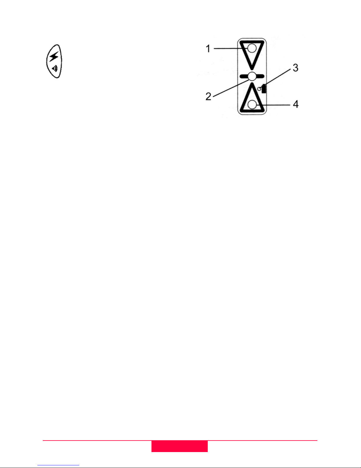
1 Red Light - High Indication
2 green Light - On-grade
3 Amber Light - Low Battery
Indication
4 Red Light - Low Indication

9Rod-Eye Mini and Basic-1.1.0en
ROD-EYE Basic (INTERIOR APPLICATIONS)
ROD-EYE Mini Brackets
A general purpose Grade Rod Bracket
comes with the ROD-EYE Mini Sensor
for mounting to grade rods. To secure
the bracket to the detector, slide the
dovetail on the bracket into the
grooves on the back of the detector. A
snapping action will ensure that the
bracket is securely attached.
To remove the bracket, depress the
thumb release tab and slide the
bracket upward.
1Bracket Locking and Release
Tab - for securing and releasing the
bracket from the sensor.
2Dovetail Slots - attached bracket
to the detector.
3Reference Indicators - aligned
with the on-grade mark of the
sensor.
4Clamping Screw - Tightens the
bracket to the grade rod.
A Safety Bracket and Strap (lanyard)
comes with the ROD-EYE Basic
Sensor for providing a safety
attachment when using the sensor's
magnetic mount attached to ceiling
grid.
1 Dovetail Slots
2 Thumb Release

10 MAINTENANCE
Rod-Eye Mini and Basic-1.1.0en
MAINTENANCE
Keep it Clean.
Clean the front of your ROD-EYE
Sensor with a mild detergent and a soft
cloth. Do not use your fingers or a dry
cloth to clean the window(s). Take care
not to scratch the glass on the laser
reception window.
The ROD-EYE Sensor contains
static sensitive components.
Do not attempt any internal repairs on
your unit. Opening the sensor will void
the warranty.
Take care of your batteries.
The ROD-EYE Sensor uses two "AA"
alkaline batteries. Remove the
batteries if the sensor is to be stored
for a period of time. Avoid extreme
temperatures that can cause battery
degradation and early failure of the
batteries.
Contact your dealer, Leica
Geosystems, or an Authorized Factory
Service Center if you have questions
regarding your ROD-EYE Mini or
ROD-EYE Basic Sensor.
This manual suits for next models
1
Table of contents
Other Leica Geosystems Accessories manuals