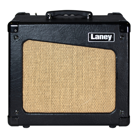
Laney AudioHub AH40 User manual


NOTE
This manual has been written for easy access of information. The
front and rear panels are graphically illustrated, with each control
and feature numbered. For a description of the function of each
control feature, simply check the number with the explanations
adjacent to each panel.
Your Laney amplifier has undergone a thorough two stage, pre-
delivery inspection, involving actual play testing.
When you first receive your Laney amplifier, follow these simple
procedures:
(i) Ensure that the amplifier is the correct voltage for the
country it is to be used in.
(ii) Connect your equipment with a high quality shielded cable.
You have probably spent considerable money on your amplifier
and equipment - don’t use poor quality cable, it won’t do your
gear justice.
Please retain your original carton and packaging so in the unlikely
event that some time in the future your amplifier should require
servicing you will be able to return it to your dealer securely
packed.
Care of your Laney amplifier will prolong it’s life.....and yours!
After unpacking your amplifier check that it is factory fitted with a
three pin ‘grounded’ (or earthed) plug. Before plugging into the
power supply ensure you are connecting to a grounded earth outlet.
If you should wish to change the factory fitted plug yourself, ensure
that the wiring convention applicable to the country where the
amplifier is to be used is strictly conformed to. As an example in
the United Kingdom the cable colour code for connections are as
follows.


INTRODUCTION
The Audiohub range of multi instrument amplifiers is designed to be the centre of your audio world. The portable AH40 and
AH80 amplifiers each feature 3 independent channels allowing connection of balanced XLR, line and Hi-
Impedance/Instruments, as well as a dedicated Aux In. The AH40 and AH80 are driven by 40W and 80W output sections
respectively. Additionally, the AH80 is equipped with a delay unit with Time and Feedback controls, and an FX send switch on
each channel.
Ideal for keyboards, vocals, electronic drums and playing recorded audio, the Audiohub series features custom drivers to
ensure that whatever sound source you use is produced and projected correctly and clearly. Add to this ‘Road Rugged’ solid
construction, carpet covering, metal grilles and specially designed kickback cabinets - the Audiohub Series is the ideal solution
for all of your audio performance and rehearsal needs.

BLOCK DIAGRAM
Internal Speakers
INTERNAL
FX
FeedbackDelay
+
-
AH80 ONLY
FX
Line
Mic
FX Level
Master Volume
Power amp
Line (R)
Line (L)
Instrument (Hi-Z)/Line
Pre Out
5 Band EQ
Headphones
FX
FX
AH80 ONLY
AH80 ONLY
Limiter
AH80 ONLY
Aux In (3.5mm)
Level
Level
Level

AH40 FRONT PANEL
1. CH1 MIC INPUT Balanced XLR input for low impedance microphone signals (200-600 Ohms).
2. CH1 LINE INPUT Unbalanced Jack input socket for connection of all line level signals (keyboard, signal processor, sample, drum machine, etc.).
Note that the Mic and Line inputs may be used simultaneously, although it may be difficult to balance input levels, depending on your source.
3. CH1 LEVEL Adjusts the channel level, enabling the user to balance levels across channels.
4. CH2 STEREO LINE INPUT 2 x Unbalanced Jack sockets for connection of a stereo line signal. Sockets may also be used to connect a single
mono source, or two individual sources. When connecting independent sources, use the output controls on your device to adjust the balance between
the two signals.
5. CH2 LEVEL See CH 1 LEVEL.
6. CH3 LINE/INSTRUMENT INPUT Unbalanced high impedance input for connection of high impedance devices such as electric guitars/basses,
or regular line devices. This channel features +6dB gain compared to the other line inputs, so take care if connecting a line level device here.
7. CH3 LEVEL See CH1 LEVEL. As this channel has more gain than the other line inputs, don’t be surprised if you find that you need to set this
control lower than the others when using line level devices.
8. GRAPHIC EQ A 5-Band graphic equaliser to fine tune your sound and help eliminate feedback issues. This is applied to the master mix. EQ is
best used subtly. Cutting or boosting all bands, or using extreme settings can reduce clarity and dynamics.
9. MASTER VOLUME Sets the overall output level of the amplifier or headphones.
10. AUX INPUT 3.5mm Stereo Jack for connection of an auxiliary source such as an MP3 player. This input is controlled by the master volume
control. The graphic equaliser has no effect on the Aux input.
11. LINE OUT Balanced line output for recording or connection to another amplifier. This output is not affected by the equaliser or master volume.
The Aux input does not appear on this output. This allows you to record your performance without the presence of a backing track.
12. PHONES Stereo headphone socket. This disconnects the internal speaker so that you can practice by yourself. Ensure that the Master Volume is
turned down before plugging in your headphones.
13. POWER LED Indicates that the unit is powered on.

AH80 FRONT PANEL
1. CH1 MIC INPUT Balanced XLR input for low impedance microphone signals (200-600 Ohms).
2. CH1 LINE INPUT Unbalanced Jack input socket for connection of all line level signals (keyboard, signal processor, sample, drum machine, etc.). Note that the Mic
and Line inputs may be used simultaneously, although it may be difficult to balance input levels, depending on your source.
3. CH1 LEVEL Adjusts the channel level, enabling the user to balance levels across channels.
4. FX SEND When pushed in, this switch routes the channel signal to the built in digital delay.
5. CH2 STEREO LINE INPUT 2 x Unbalanced Jack sockets for connection of a stereo line signal. Sockets may also be used to connect a single mono source, or two
individual sources. When connecting independent sources, use the output controls on your device to adjust the balance between the two signals.
6. CH2 LEVEL & FX See CH 1 LEVEL & FX.
7. CH3 LINE/INSTRUMENT INPUT Unbalanced high impedance input for connection of high impedance devices such as electric guitars/basses, or regular line
devices. This channel features +6dB gain compared to the other line inputs, so take care if connecting a line level device here.
8. CH3 LEVEL & FX See CH1 LEVEL & FX. As this channel has more gain than the other line inputs, don’t be surprised if you find that you need to set this control
lower than the others when using line level devices.
9. DELAY TIME Controls the amount of time between repeats of the inbuilt delay. Turning this control clockwise will increase the delay time.
10. DELAY FEEDBACK This controls the amount of repeats in the inbuilt delay. Turning the control clockwise increases the amount of repeats.
11. DELAY LEVEL Controls the mix level of the inbuilt delay. Use the delay to add atmosphere to your sound, or to create interesting effects.
12. GRAPHIC EQ A 5-Band graphic equaliser to fine tune your sound and help eliminate feedback issues. This is applied to the master mix. EQ is best used subtly.
Cutting or boosting all bands, or using extreme settings can reduce clarity and dynamics.
13. MASTER VOLUME Sets the overall output level of the amplifier or headphones.
14. AUX INPUT 3.5mm Stereo Jack for connection of an auxiliary source such as an MP3 player. This input is controlled by the master volume control. The graphic
equaliser has no effect on the Aux input.
15. LINE OUT Balanced line output for recording or connection to another amplifier. This output is not affected by the equaliser or master volume. The Aux input does
not appear on this output. This allows you to record your performance without the presence of a backing track.
16. PHONES Stereo headphone socket. This disconnects the internal speaker so that you can practice by yourself. Ensure that the Master Volume is turned down
before plugging in your headphones.
17. POWER LED Indicates that the unit is powered on.

AH40/AH80 REAR PANEL
(AH80 SHOWN. AH40 SIMILAR)
18. VOLTAGE SELECT SWITCH This is factory set to the correct voltage for the region the product is supplied to. If necessary it can be reset by
removing the mains lead and then loosening (but not removing) the screws securing the cover. The cover can then be pivoted away from the switch which
can be moved to select the alternate voltage. DO NOT reconnect the mains lead until the cover is replaced and secured. Please ensure the correct fuse is
fitted (as printed on the panel) for the voltage being used.
19. MAINS INLET SOCKET Connect to your power source using the supplied cable.
20. MAINS FUSE This drawer contains the main safety fuse for the unit. USE ONLY THE CORRECT SIZE AND RATING SPECIFIED ON THE PANEL.
21. MAINS POWER SWITCH When turned on, the Power LED on the front panel will light.
General Notes
Amplifier connection: In order to avoid damage, it is advisable to establish and follow a pattern for turning on and off your equipment. With all
system parts connected, turn on source equipment, tape decks, cd players, mixers, effects processors etc. BEFORE turning on your AUDIOHUB.
Many products have large transient surges at turn on and off which can cause damage to your speakers. By turning on your AUDIOHUB LAST and
making sure its Volume control is set to minimum any transients from other equipment will not reach your loudspeakers. Wait until all system
parts have stabilised; usually a couple of seconds. Similarly when turning off your system always turn down the Volume control on your
AUDIOHUB and then turn off its power before turning off other equipment.
Caution: These professional loudspeaker systems are capable of generating very high sound pressure levels. Use care with placement and
operation to avoid exposure to excessive levels that can cause permanent hearing damage. (Refer to guidelines on page 2)
Servicing: The user should not attempt to service these products. Refer all servicing to qualified service personnel.

SAMPLE SETUP
RECORD OUT
MP3
KEYBOARD
BASS
MIC

Other manuals for AudioHub AH40
1
This manual suits for next models
1
Table of contents
Other Laney Amplifier manuals

Laney
Laney KB30 User manual

Laney
Laney LX20 User manual

Laney
Laney Nexus FET NXF User manual

Laney
Laney Tube Fusion User manual

Laney
Laney Alliance VC50 User manual

Laney
Laney A50 User manual

Laney
Laney A1 User manual

Laney
Laney LX120H User manual

Laney
Laney Alliance VH100R User manual

Laney
Laney LA35C User manual

Laney
Laney LC30-112 User manual

Laney
Laney LC30-II User manual

Laney
Laney GS212IE User manual

Laney
Laney KB30 User manual

Laney
Laney LX12 User manual

Laney
Laney LX35D User manual

Laney
Laney Lionheart L5-Studio User manual

Laney
Laney LG35R User manual

Laney
Laney Prism P65 User manual

Laney
Laney BC 250 User manual