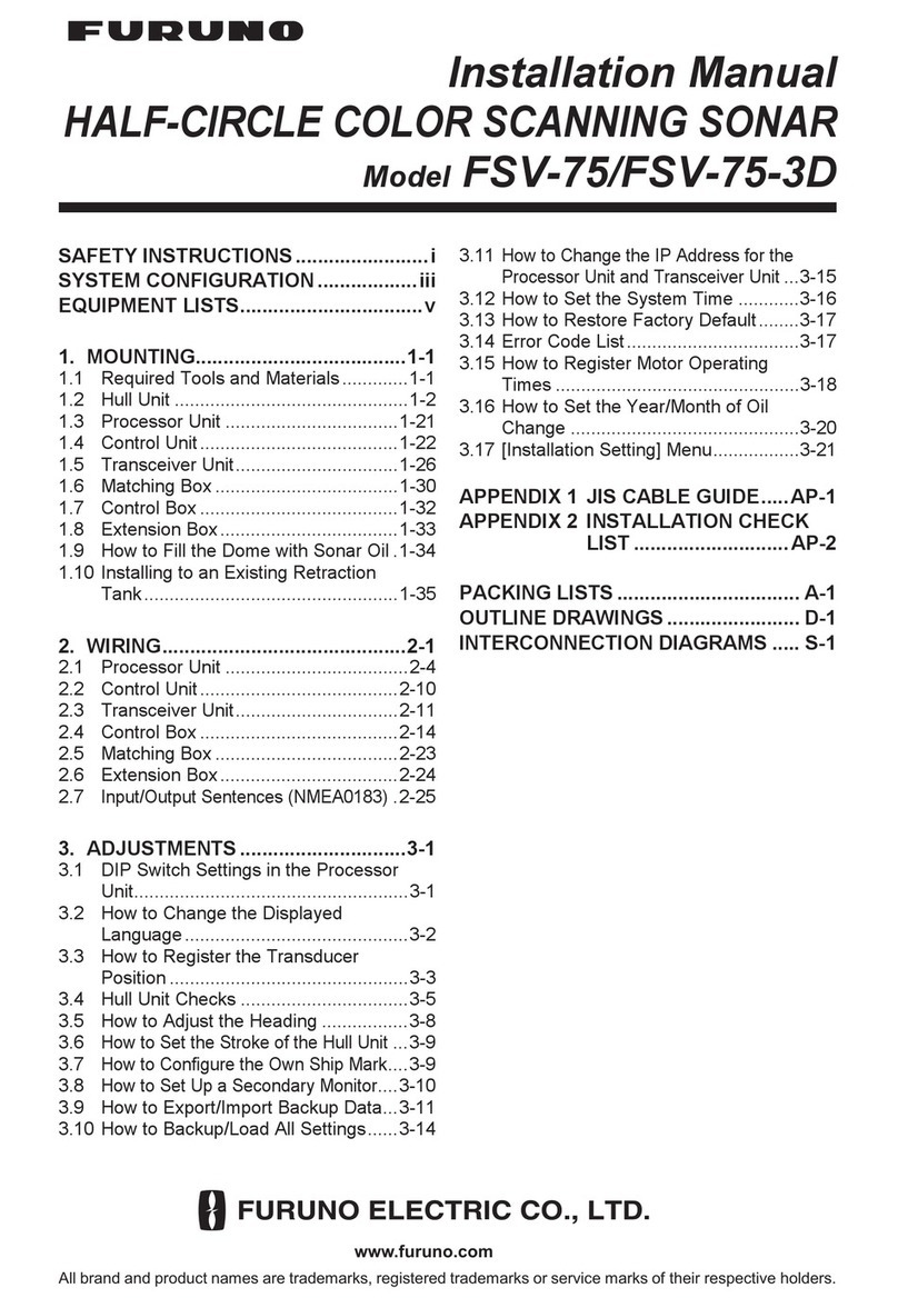
JW Fishers SCAN-650 User manual

1
SCAN-650
Scanning Sonar
OPERATION MANUAL
JW FISHERS MFG INC
rev 811
JW FISHERS MFG INC
1953 COUNTY ST.
E. TAUNTON, MA 02718 USA
(508) 822-7330; (800) 822-4744; FAX (508) 880-8949

2
SCAN-650
Scanning Sonar
OPERATION
AND
MAINTENANCE
MANUAL
JW FISHERS MFG INC
1953 COUNTY ST.
E. TAUNTON, MA 02718 USA
(508) 822-7330; (800) 822-4744; FAX (508) 880-8949
Surface Sonar Processor Included

3
TABLE OF CONTENTS
• CAUTIONS............................................................................................................. 4
• SPECIFICATIONS AND OPTIONS ........................................................................ 5
• MINIMUM SYSTEM REQUIREMENTS................................................................. 6
• INTRODUCTION.................................................................................................... 7
• SYSTEM COMPONENTS..................................................................................... 9
• THEORY OF OPERATION .................................................................................. 11
• OPERATOR SWITCHES AND CONTROLS ....................................................... 16
• INSTALLING HARDWARE AND SOFTWARE .................................................... 27
• CABLING THE SYSTEM ..................................................................................... 31
• ATTACHING TO ROV.......................................................................................... 32
• OPERATION ........................................................................................................ 35
• SAMPLE PLAYBACK........................................................................................... 36
• SAMPLE RECORDING ....................................................................................... 37
• FAQs .................................................................................................................... 39
• TROUBLESHOOTING......................................................................................... 41
• APPENDIX A (configuring GPS) .......................................................................... 44
• APPENDIX B (USB to Serial Adaptor)................................................................. 45
• MAINTENANCE................................................................................................... 47
• WARRANTY......................................................................................................... 47

4
CAUTIONS:
• Do not allow the SCAN-650 to be exposed to excessive heat by leaving it in direct
sunlight or inside of a closed vehicle on a hot day. Excessive heat can buildup
inside the housing which can damage the electronics and/or destroy the waterproof
seals.
• Take special care of the black flexible boot located on the top of the scanning head.
The black flexible boot is an acoustic window that should be keep clean (soap and
water) and protected from damage.
• Do not remove the (6) screws that hold the black flexible boot in place on the scan-
ning head in-place. The scanning head contains a liquid that will drain out if the
screws are loosened.
• Do not remove the black hex head bolt on the scanning head (this is only on the 2
piece SCAN-650).
• When mounting the scanning head, be sure the arrow on top of the scanning head is
pointing forward, this will be the top of the screen on the PC.

5
SPECIFICATIONS
PERFORMANCE/DESCRIPTION:
•Frequency............................................................................................................ 650 kHz.
•Beamwidth-horizontalxvertical .......................................................... 2.4 deg by 40 deg.
• Ranges: ........................................................................................ 5, 10, 20, 40, 60 meters
. .................................................................................................. 16.5, 33, 66,132,198 feet
• Max depth ............................................................................................... 300 m / 1,000 ft .
• Input voltage
- Sonar Processor .......................................................... 9-12 vdc or 120/220 vac (5 watt).
- Scanning Head................................................ from Sonar Processor or 9-36 from ROV.
• Cable ..................................................................................................... 2 or 4 conductor.
DIMENSIONS/WEIGHT:
• Sonar Processor..................................... 8”Wx9"Dx2.5"H ......................... 2 lbs / 0.9 Kg.
650A:
• Scanning Head and housing ................... 3.5"Dia x 10.5"L ................. 3.6 lbs 1.6 Kg (air).
............................. 0 lbs / 0 Kg (water).
650B:
• Scanning Head ......................................... 3.5"Dia x 4"L ................... 1.4 lbs / .6 Kg. (air).
.......... .375 lbs / .17 Kg. (water).
• Housing ..................................................... 3.5”Dia x 9"L..................... 2.8 lbs 1.2 Kg (air).
..................... 0 lbs / 0 Kg (water).
Note:
If 180° sweep, cut times in half; if 90° sweep, cut times by four, etc.
OPTIONS
• up to 600 meters / 2,000 feet of cable
• Carrying case

6
SCAN-650 MINIMUM SYSTEM REQUIREMENTS
CPU: Intel or AMD. 500MHz
System memory: 64 Mb RAM
(Faster CPU and more RAM will allow faster scanning)
One available USB port
Windows 98 or later
15 Mb of free disk space for program installation
Disk space for file recording:
5 Meter Range
.5 deg step............... 52 meg/hr ............ 13 hrs/CD, 90 hrs/DVD
2 deg step ................ 30 meg/hr ............ 23 hrs/CD, 200 hrs/DVD
10 Meter Range
.5 deg step............... 27 meg/hr ............ 25 hrs/CD, 170 hrs/DVD
2 deg step ................ 17 meg/hr ............ 39 hrs/CD, 270 hrs/DVD
60 Meter Range
.5 deg step............... 14 meg/hr ............ 50 hrs/CD,345 hr/DVD
2 deg step ................ 11.5 meg/hr ......... 60 hr/CD, 400 hr/DVD
Video Card capable of:
16 bit color
Screen Area of 800 x 600 pixels (minimum)
Optional:
CD or DVD burner for archiving files
Note: For the fastest scanning capability, shut down all other programs (including
virus scan).

7
INTRODUCTION
The SCAN-650 is a high performance imaging sonar system available in two different package
configurations which enables it be used on large or small ROVs. It can also be pole-mounted and
used from a small boat in shallow water.
The Sonar Processor is located in the boat and
allows fine tuning of the signal from the electronics
module prior to being displayed and recorded on
the PC display. It is used with both of the above
models. The Sonar Processor also includes an
interface for a GPS receiver.
The SCAN-650A configuration is used with
larger ROVs, or when the main application is
boat deploying the unit on a pole (see photo next page).
The black scanning head is connected permanently to
the electronics module. A cable (not shown) comes out
of the bottom of the electronics module and connects
to the Sonar Processor.
The SCAN-650B configuration is used with
smaller ROVs. The black scanning head is mounted
to the front of the ROV and a short cable connects the
head to the electronics module which is mounted on the
side or under the ROV. Cabling options include a hardwired
version where a cable comes out of the bottom of the of the
electronics module and connects directly to the Sonar Pro-
cessor or a set of short wires equipped with under water con-
nectors and a hull penetrator. This option allows the wiring from
the scanning head to enter the ROV. The scannin head can
draw power from the ROV and utilize (2) spare wires in the ROV
umbilical cable for communication with the Sonar Processor.

8
When operating in shallow water, the
scanning head can taped or clamped to
a pole and deployed over the side of a
boat or off a dock. Pole must be held very
steady (and no waves if deployed from a
boat) to insure a clear picture. If the sur-
face conditions are too rough, the scan-
ning head can be attached to a tripod and
lowered to the bottom (2’ off bottom for
small targets) to provide clear images.
There are times when it is advantages to
deploy the scanning head inverted (up-
side down). This might occur when de-
ploying on a pole. The software allows
inverted scanning (see “Settings” Menu
pg 18 .)
The target below is a pickup truck (note large
black shadow) located in 18 feet of water. The
scanning head was mounted on a pole which
was deployed from a small boat (see top photo).
The most common application is mounting the scanning head
on an ROV. The ROV can rest on the bottom or hover just off the
bottom and the sonar scans 360 degrees looking for targets.
Mountingthescanning
headon apole allows
it to be deployed from
aboat in shallow
water.
SCAN-650scanning head
mountedon Fishers SeaLion
ROV.
123
1
2
3
1
2
3
123
Pole
Transducer(black end) is
positioneddownwardwhen
operating with a pole. Be
suretransduceris below
bottom of pole (so pole
doesnotinterfere with
signal).
SCAN-650
1234
1
23
4
1
23
4
1234
12
12
SCAN-650
Tripod deployment

9
SYSTEM COMPONENTS
Signalsfromthescanninghead travelupthecabletotheSonarProcessoronthesurface.The
signalsareprocessedandsenttothePCwherethesignalisdisplayedandrecorded.Theboat’sGPS
receiver can also be connected to the Sonar Processor. If connected, the boat’s Latitude and
Longitudewill be displayed and recorded by the PC.
cable to surface
Sonar
Processor
12345
1
234
5
1
234
5
12345
PC (customer supplied)
Boat’s
GPS
USB Port
The Sonar Processor can be powered by 9 - 12 vdc.A 120/220 vac to 12 vdc wall transformer is
suppliedto power the system from a 120/220 ac voltagesupply. Acable withbattery clips is
suppliedto power thesonarfrom a 12voltbattery.
WallTransformer Cable for 12v battery
Transducer Head and
Electronics
TheSonar Processor connectto any availableUSB portonthe PC. (Note: Itis best touse the
samephysical USB porteverytime you operate)

10
LEFT
BLANK
This manual suits for next models
2
Table of contents
Other JW Fishers Sonar manuals