
JVC KD-G465 User manual

SERVICE MANUAL
COPYRIGHT © 2005 Victor Company of Japan, Limited No.MA137
2005/3
CD RECEIVER
MA13720053
KD-G465
TABLE OF CONTENTS
1 PRECAUTIONS . . . . . . . . . . . . . . . . . . . . . . . . . . . . . . . . . . . . . . . . . . . . . . . . . . . . . . . . . . . . . . . . . . . . . . . 1-3
2 SPECIFIC SERVICE INSTRUCTIONS . . . . . . . . . . . . . . . . . . . . . . . . . . . . . . . . . . . . . . . . . . . . . . . . . . . . . . 1-6
3 DISASSEMBLY . . . . . . . . . . . . . . . . . . . . . . . . . . . . . . . . . . . . . . . . . . . . . . . . . . . . . . . . . . . . . . . . . . . . . . . 1-7
4 ADJUSTMENT . . . . . . . . . . . . . . . . . . . . . . . . . . . . . . . . . . . . . . . . . . . . . . . . . . . . . . . . . . . . . . . . . . . . . . . 1-25
5 TROUBLESHOOTING . . . . . . . . . . . . . . . . . . . . . . . . . . . . . . . . . . . . . . . . . . . . . . . . . . . . . . . . . . . . . . . . . 1-26
Area suffix
UT ------------------------ Taiwan
UH --------------------- Thailand
UN --------------------- Indonesia
U ------------------- Other Areas

1-2 (No.MA137)
SPECIFICATION
• Design and specifications are subject to change without notice.
• Microsoft and Windows Media are either registered trademarks or trademarks of Microsoft Corporation in the United States and/
or other countries.
AUDIO AMPLIFIER SECTION
Maximum Power Output Front 50 W per channel
Rear 50 W per channel
Continuous Power Output (RMS) Front 19 W per channel into 4 Ω, 40 Hz to 20 000 Hz at no more
than 0.8% total harmonic distortion.
Rear 19 W per channel into 4 Ω, 40 Hz to 20 000 Hz at no more
than 0.8% total harmonic distortion.
Load Impedance 4 Ω(4 Ωto 8 Ωallowance)
Tone Control Range Bass ±10 dB at 100 Hz
Treble ±10 dB at 10 kHz
Frequency Response 40 Hz to 20 000 Hz
Signal-to-Noise Ratio 70 dB
Line-Out Level/Impedance 2.0 V/20 kΩload (full scale)
Output Impedance 1 kΩ
Other Terminals CD changer
TUNER SECTION
Frequency Range FM 87.5 MHz to 108.0 MHz
AM 531 kHz to 1 602 kHz
FM Tuner Usable Sensitivity 11.3 dBf (1.0 µV/75 Ω)
50 dB Quieting Sensitivity 16.3 dBf (1.8 µV/75 Ω)
Alternate Channel Selectivity (400 kHz) 65 dB
Frequency Response 40 Hz to 15 000 Hz
Stereo Separation 30 dB
Capture Ratio 1.5 dB
AM Tuner Sensitivity 20 µV
Selectivity 35 dB
CD PLAYER SECTION
Type Compact disc player
Signal Detection System Non-contact optical pickup (semiconductor laser)
Number of channels 2 channels (stereo)
Frequency Response 5 Hz to 20 000 Hz
Dynamic Range 96 dB
Signal-to-Noise Ratio 98 dB
Wow and Flutter Less than measurable limit
MP3 decoding format MPEG1/2 Audio Layer 3
Max. Bit Rate: 320 kbps
WMA (Windows Media Audio) decoding format Max. Bit Rate: 192 kbps
GENERAL
Power Requirement Operating Voltage DC 14.4 V (11 V to 16 V allowance)
Grounding System Negative ground
Allowable Operating Temperature 0°C to +40°C
Dimensions (W ×H ×D) Installation Size (approx.) 182 mm ×52 mm ×150 mm
Panel Size (approx.) 188 mm ×58 mm ×11 mm
Mass (approx.) 1.4 kg (excluding accessories)

(No.MA137)1-3
SECTION 1
PRECAUTIONS
1.1 Safety Precautions
!Burrs formed during molding may be left over on some parts of the chassis. Therefore,
pay attention to such burrs in the case of preforming repair of this system.
!Please use enough caution not to see the beam directly or touch it in case of an
adjustment or operation check.

1-4 (No.MA137)
1.2 Preventing static electricity
Electrostatic discharge (ESD), which occurs when static electricity stored in the body, fabric, etc. is discharged, can destroy the laser
diode in the traverse unit (optical pickup). Take care to prevent this when performing repairs.
1.2.1 Grounding to prevent damage by static electricity
Static electricity in the work area can destroy the optical pickup (laser diode) in devices such as CD players.
Be careful to use proper grounding in the area where repairs are being performed.
(1) Ground the workbench
Ground the workbench by laying conductive material (such as a conductive sheet) or an iron plate over it before placing the
traverse unit (optical pickup) on it.
(2) Ground yourself
Use an anti-static wrist strap to release any static electricity built up in your body.
(3) Handling the optical pickup
• In order to maintain quality during transport and before installation, both sides of the laser diode on the replacement optical
pickup are shorted. After replacement, return the shorted parts to their original condition.
(Refer to the text.)
• Do not use a tester to check the condition of the laser diode in the optical pickup. The tester's internal power source can easily
destroy the laser diode.
1.3 Handling the traverse unit (optical pickup)
(1) Do not subject the traverse unit (optical pickup) to strong shocks, as it is a sensitive, complex unit.
(2) Cut off the shorted part of the flexible cable using nippers, etc. after replacing the optical pickup. For specific details, refer to the
replacement procedure in the text. Remove the anti-static pin when replacing the traverse unit. Be careful not to take too long a
time when attaching it to the connector.
(3) Handle the flexible cable carefully as it may break when subjected to strong force.
(4) It is not possible to adjust the semi-fixed resistor that adjusts the laser power. Do not turn it.
1.4 Attention when traverse unit is decomposed
*Please refer to "Disassembly method" in the text for the CD pickup unit.
• Apply solder to the short land before the flexible wire is disconnected from the connector on the CD pickup unit.
(If the flexible wire is disconnected without applying solder, the CD pickup may be destroyed by static electricity.)
• In the assembly, be sure to remove solder from the short land after connecting the flexible wire.
1M
(caption)
Anti-static wrist strap
Conductive material
(conductive sheet) or iron plate
Pickup
Short-circuit point
(Soldering)
Flexible wire

(No.MA137)1-5
1.5 Important for laser products
1.CLASS 1 LASER PRODUCT
2.DANGER : Invisible laser radiation when open and inter
lock failed or defeated. Avoid direct exposure to beam.
3.CAUTION : There are no serviceable parts inside the
Laser Unit. Do not disassemble the Laser Unit. Replace
the complete Laser Unit if it malfunctions.
4.CAUTION : The CD,MD and DVD player uses invisible
laser radiation and is equipped with safety switches which
prevent emission of radiation when the drawer is open and
the safety interlocks have failed or are defeated. It is
dangerous to defeat the safety switches.
5.CAUTION : If safety switches malfunction, the laser is able
to function.
6.CAUTION : Use of controls, adjustments or performance of
procedures other than those specified here in may result in
hazardous radiation exposure.
REPRODUCTION AND POSITION OF LABELS
!
Please use enough caution not to
see the beam directly or touch it
in case of an adjustment or operation
check.
WARNING LABEL
CAUTION : Visible and Invisible
laser radiation when open and
interlock failed or defeated.
AVOID DIRECT EXPOSURE TO
BEAM. (e)
VARNING : Synlig och
osynling laserstrålning när
den öppnas och spärren är
urkopplad. Betrakta ej
strålen. (s)
VARO : Avattaessa ja suojalukitus
ohitettuna tai viallisena olet alttiina
näkyvälle ja näkymättömälle
lasersäteilylle. Vältä säteen
kohdistumista suoraan itseesi. (f)
ADVARSEL : Synlig og usynlig
laserstråling når maskinen er
åben eller interlocken fejeler.
Undgå direkte eksponering til
stråling. (d)
CLASS 1
LASER PRODUCT
1-6 (No.MA137)
SECTION 2
SPECIFIC SERVICE INSTRUCTIONS
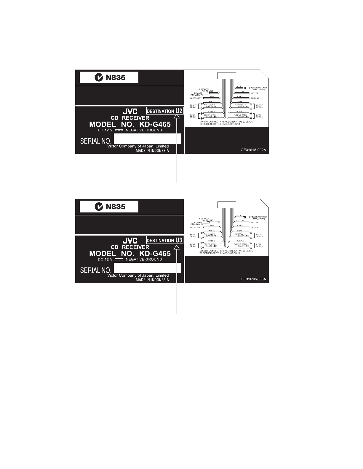
2.1 HOW TO IDENTIFY MODELS
2.1.1 NAME PLATE
Discernment sign
Discernment sign

(No.MA137)1-7
SECTION 3
DISASSEMBLY
3.1 Main body section
3.1.1 Removing the front panel assembly
(See Fig.1)
(1) Push the detach button in the lower right part of the front
panel assembly and remove the front panel assembly.
Fig.1
3.1.2 Removing the bottom cover
(See Fig.2)
(1) Turn the main body up side down.
(2) Insert a screwdriver under the joints to release the two
joints aon the left side, two joints bon the right side and
joint con the back side of the main body, then remove the
bottom cover from the main body.
Note:
When releasing the joints using a screwdriver, do not damage
the main board.
Fig.2
3.1.3 Removing the front chassis assembly
(See Fig.3)
• Prior to performing the following procedures, remove the front
panel assembly and bottom cover.
(1) Remove the two screws Aon the both sides of the main
body.
(2) Release the two joints dand two joints eon the both sides
of the main body, then remove the front chassis assembly
toward the front.
Fig.3
Front panel assembly
Detach button
Bottom cover
Joint b
Joint b
Joint c
Joint a
Joint a
Joint d
Front chassis assembly
A
Joint e
Joint d Joint e

1-8 (No.MA137)
3.1.4 Removing the side panel
(See Fig.4)
• Prior to performing the following procedure, remove the front
panel assembly as required.
(1) Remove the screw Band two screws Cattaching the side
panel on the left side of the main body, and take out the
side panel.
Fig.4
3.1.5 Removing the rear bracket
(See Fig.5)
• Prior to performing the following procedure, remove the bottom
cover.
(1) Remove the three screws D, three screws Eand three
screws Fattaching the rear bracket on the back side of the
main body.
(2) Take out the rear bracket.
Fig.5
3.1.6 Removing the main board
(See Fig.6)
• Prior to performing the following procedures, remove the front
panel assembly, bottom cover, front chassis assembly, side
panel and rear bracket.
(1) Remove the two screws Gattaching the main board.
(2) Disconnect the connector CN501 on the main board from
the main body and take out the main board.
Fig.6
Side panel
CBC
EF
DD
E
Rear bracket F
Main board
G
G
CN501
(No.MA137)1-9
3.1.7 Removing the CD mechanism assembly
(See Fig. 7)
• Prior to performing the following procedures, remove the front
panel assembly, bottom cover, front chassis assembly, side
panel, rear bracket and main board.
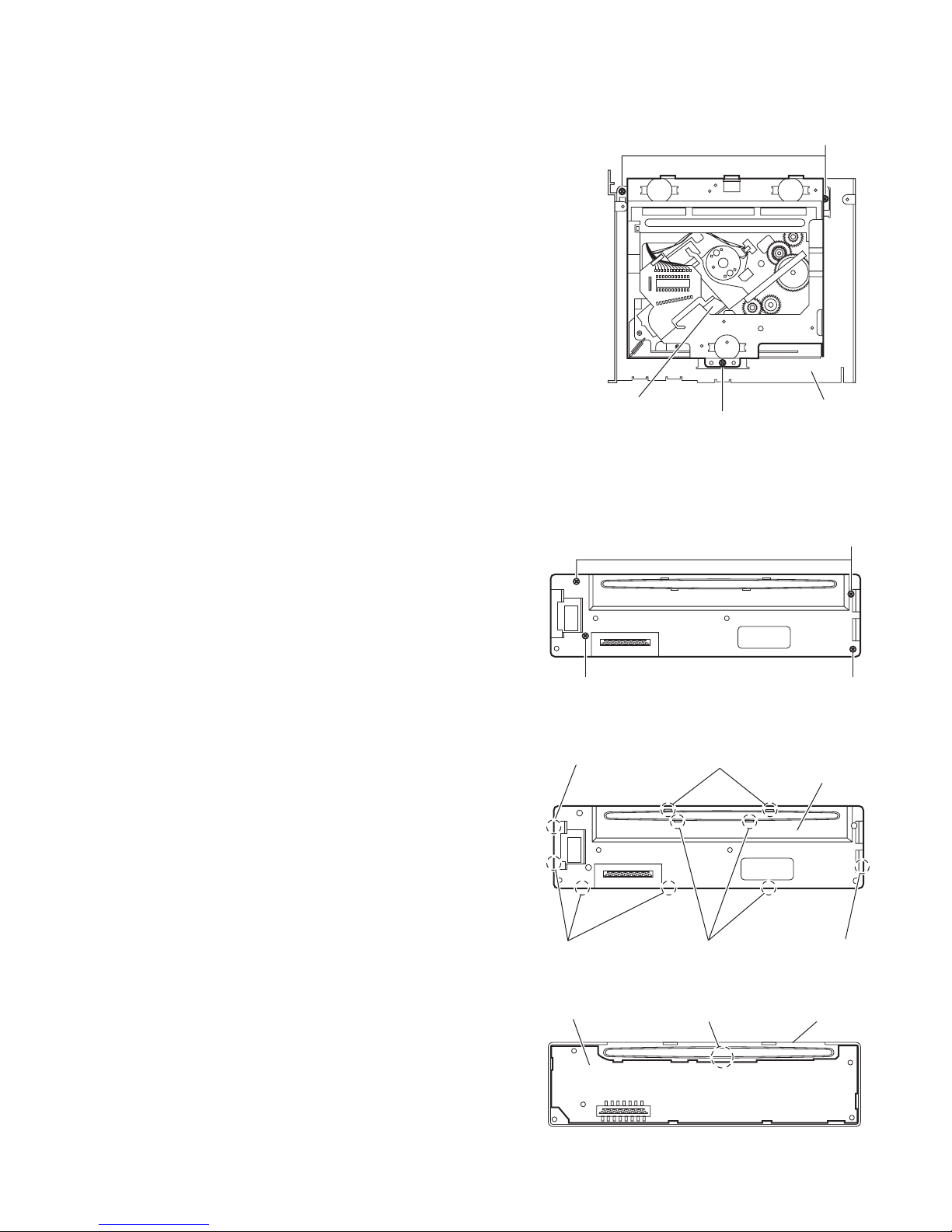
(1) Remove the three screws Hattaching the CD mechanism
assembly on the top chassis.
(2) Take out the CD mechanism assembly.
Fig.7
3.1.8 Removing the switch board
(See Figs.8 to 10)
• Prior to performing the following procedures, remove the front
panel assembly.
(1) Remove the four screws Jon the back side of the front pan-
el assembly. (See Fig.8)
(2) Release the ten joints fand remove the rear cover. (See
Fig.9)
(3) Release the joint gand take out the switch board from the
front panel assembly. (See Fig.10)
Fig.8
Fig.9
Fig.10
H
H
CD mechanism assembly Top chassis
J
J
J
Joints f
Joint fJoints f
Joints fJoint f
Rear cover
Switch board Joint g Front panel assembly

1-10 (No.MA137)
3.2 CD Mechanism Assembly
3.2.1 Removing the top cover
(See Figs.1 and 2)
(1) Remove the two screws Aon the both side of the body.
(2) Lift the front side of the top cover and move the top cover
backward to release the two joints a.
Fig.1
Fig.2
A
A
A
Joints a
Top cover
Joints a
Top cover
Other manuals for KD-G465
3
Table of contents
Other JVC Car Receiver manuals


