
impact VC-500WLN User manual

INSTRUCTIONS
VC-500WLN
Digital Monolight

2
Thank you for choosing the Impact VC-500WLN Digital Monolight, or the
VC-500WL2KN and VC-500WL3KN Digital Monolight Kits. This professional-grade
studio lighting unit features a user-replaceable 250 W halogen modeling light
and a 500 Ws ash tube. The monolight is constructed with a durable housing
and boasts a lightning fast 1.5 second recycle time, intelligent adaptive thermal
control, and CMOS chip circuitry.
The powerful Impact Digital Monolight has an integrated 2.4 GHz, 16-channel
wireless radio receiver. You can trigger the monolight from a distance of 328
feet (100 m) when it’s partnered with the VC-500WLXMT transmitter (included
with kits only, sold separately). Paired with the unit’s integrated group functions,
you can arrange and digitally segment each of their remote devices as needed.
Additionally, the ash’s seven optical slave modes enable the device to
communicate with your on-camera master ashes, seamlessly triggering up to
six preashes.
Features
• Fast recycle time and ash duration
• Integrated 2.4 GHz wireless receiver
• 250 W user-replaceable halogen modeling light
• Adaptive thermal control
• CMOS chip circuitry
• Compatible with S-mount accessories
• Low 5 V trigger voltage
• Quiet fan cooling
Introduction

3
VC-500WL3KN
• Digital Monolight (×3)
• Reector (×3)
• 9 ft. air-cushioned light
stand (×3)
• 40 in. umbrella—white with
black backing (×3)
• 24 × 36 in. softbox with
speed ring
• Wireless controller
• AC cable (×3)
• 250 W modeling lamp (×3)
• Flash tube (installed) (×3)
• Spare fuse (in fuse bay) (×3)
• Protective cover (×3)
• Wheeled kit case
• User manual
VC-500WL2KN
• Digital Monolight (×2)
• Reector (×2)
• 8 ft. air-cushioned light
stand (×2)
• 40 in. umbrella—white with
black backing (×2)
• 24 × 36 in. softbox with
speed ring
• Wireless controller
• AC cable (×2)
• 250 W modeling lamp (×2)
• Flash tube (installed) (×2)
• Spare fuse (in fuse bay) (×2)
• Protective cover (×2)
• Wheeled kit case
• User manual
VC-500WLN
• Digital Monolight
• Reector
• AC cable
• 250 W modeling lamp
• Flash tube (installed)
• Spare fuse (in fuse bay)
• Protective cover
• User manual
Box Contents

4
Precautions
• DANGER: high-voltage parts inside.
• There are no serviceable parts inside the unit. Only qualied service engineers
should access the inside of the casing.
• If the ash tube or modeling light becomes cracked or damaged in any way,
replace immediately.
• Keep this product away from water and any ammable gases or liquids.
• Use only the correct, recommended voltage.
• Avoid rapid, high-power ashing.
• Excessive heat shortens the life span of ash tubes, modeling lamps, and internal
components.
• If the unit is not used for two months, turn it on for 30 minutes, and re the ash
several times to charge the capacitors.
• Always remove the protective cap before plugging in or powering on the unit.
• Never operate the ash with the protective cap on.
• Make sure this product is powered off when plugging it into a power source.
• Turn off the power and unplug the power cord from the unit and wall when the
monolight is not in use.
• Always remove the modeling lamp and attach the protective cap when transporting
the unit.
• Do not attempt to disassemble or repair this product. There are components inside
that can produce a hazardous electric shock.
• Handle this product with care.
• Do not stare at the lights when they are powered on.
• Clean this product with only a soft, dry cloth.
• Always wear cotton gloves when handling the ashtube.
• Keep this product away from children.
• Make sure everything is secure before proceeding.
• Make sure that this product is intact and that there are no missing parts before use.
• All images are for illustrative purposes only.

5
6
1
4
3
5
Overview
Front Side:
1. Monolight
2. Mount release
3. Modeling lamp
4. Reector
5. Flashtube
Top:
6. Optical sensor
2

6
Back:
1. LCD screen
2. Power input jack
3. Fuse bay
4. 1/4"(6.35 mm) sync port
5. Power switch
6. Modeling light and power output
adjustment dial
7. Test button
8. Audio button
9. Up and down buttons
10. Power indicator
11. Modeling light mode indicators
12. Slave mode button
13. Slave LED indicator
14. Umbrella mount tightening knob
15. Umbrella mount
16. Stand mount adjustment knobs
17. Stand mount
Overview (continued)
1
12
13
2
3
9 8 7
4 5 6
17
15
14
16
10
11
7
Remote Guide (Kits Only)
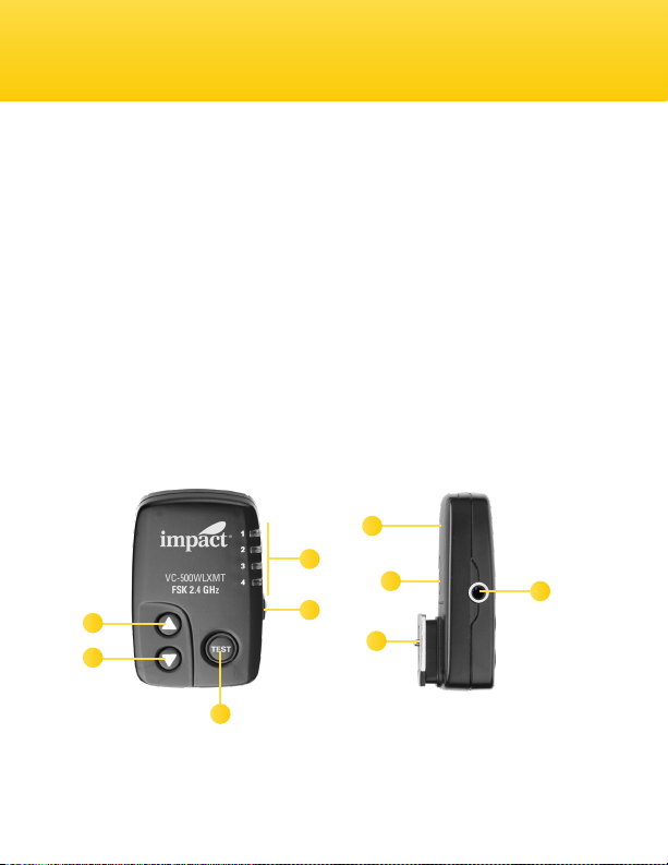
Top:
1. Up button
2. Down button
3. Test button
4. Group indicators
Right Side:
5. Group selector button
Left Side:
6. Battery compartment
Bottom:
7. Channel DIP switches
8. Hot-shoe mount
9. 3.5 mm sync port
9
1
2
3
5
4
8
6
7

8
Overview (continued)
Mode 1
Menus
Mode 2
Optical slave
menu (0–7)
Time frame Block time
Channel selector
(1–16)
Group selector
(A–D)

9
The Impact Digital Monolight includes a preinstalled ash
tube and a modeling lamp that’s packed separately in the
box. Both lights are user replaceable. Be careful not to
touch the ash tube with your bare hands, since this could
cause damage to it. Use cotton gloves or a soft, dry cloth
when touching or handling the ash tube.
The monolight’s modeling lamp is a halogen bulb within a glass sleeve. You can
touch this glass without cotton gloves. However, wiping it with a cotton cloth
after handling it is recommended. To install the modeling lamp, see Installation
and Replacement Guide on page 23.
The monolight ships with a protective cap. Always remove
the protective cap before plugging in or powering on the
unit. To remove the cap, push back the mount release and
turn the cap counterclockwise. Pull the cap from the mount,
and place it to the side for later use.
Attach the reector by aligning the lugs and making sure the umbrella hole is
on the bottom. Push back the mount release, fully insert the reector, and turn it
clockwise. You’ll hear it click into place. Let go of the mount release.
Mounting Accessories
Light Stand Mount
The Impact Digital Monolight has a standard 5/8″stand
mount with tilt and tightening knobs. To mount the monolight
on a light stand, place the stand mount onto a compatible
stand with a standard 5/8″top mount. Turn the tightening
Preparing for Use
Channel selector
(1–16)
Group selector
(A–D)

10
knob to secure. Turn the adjustment knob counterclockwise to adjust the tilt of
the monolight. Turn the knob clockwise to secure the monolight in place.
Accessory S-mount
The Digital Monolight has an S-mount for light-modifying accessories. This can
be used with optional add-ons such as speed rings for softboxes. The included
umbrella reectors line up with the units’ umbrella mounts located on the
stand mounts.
To use accessories with the monolights’ S-mount, align the accessory with the
mount and insert. Once inserted, rotate the accessory clockwise to secure. To
remove it from the mount, hold down the mount release and rotate the
accessory counterclockwise.
Umbrella Mount
To mount an umbrella
to the monolight, rst
attach the reector
using the above
instructions. Then
run the umbrella rod
through the reector’s
umbrella hole and into
the monolight’s umbrella mount. Secure the umbrella by tightening the umbrella
locking knob.
Note: Umbrellas are included only with two- and three-light kits. Umbrellas can
be purchased separately for the VC-500WLN.
Mounting Accessories (continued)
This manual suits for next models
2
Table of contents
Other impact Light Fixture manuals


Popular Light Fixture manuals by other brands

Emos
Emos CLASSIC ZY1431T manual

Westinghouse
Westinghouse Outdoor Lighting Fixture owner's manual

Hedler
Hedler C 12 silent Operation manual
Blizzard Lighting
Blizzard Lighting Puck: CSI manual

Energetic Lighting
Energetic Lighting ELYSL-5004 Series installation instructions

Lightmaxx
Lightmaxx Shaft 5R user manual


Cooper Lighting
Cooper Lighting Halo L3232E Specification sheet

Stageline
Stageline ODW-2410RGBW instruction manual

Light Sky
Light Sky Tornado Series user manual

Lightolier
Lightolier Paralyte 2424 PLA2G9LS26U specification

Lightolier
Lightolier Lytespan 83ED17S specification

Lightolier
Lightolier Calculite CS8226 specification