IDEC HR6S Series User manual

Safety Relay Modules
HR6S
Improve productivity with predictive maintenance
of safety systems
Safety Relay Modules

2
Safety Relay Modules for IoT
The basis of a functional safety system is to use diagnosis to detect failures.
Redundant control systems, for example, maintain safety by detecting the occurrence of a single failure, and at the same time give user the
opportunity to replace parts. This concept, which was introduced through international standards in 1999, has adopted throughout the world
the idea of safety by control based on safety relay modules.
With the recent progress of IT technology, IoT is being promoted at factories around the world for the purpose of optimizing productivity.
The optimal allocation of resources and predictive maintenance are important in such factories. However, predictive maintenance for safety
systems that directly inuence machine operation is especially important, and is indispensable for achieving both productivity and safety.
The HR6S safety relay module has advanced diagnostic functions, and can output the results. The diagnostic function, which is backed by
international standards, monitors the safety relay module and the devices that are connected to it, and contributes to predictive maintenance
for the safety system.

Interlock switch
Contactor
Power supply
Emergency stop
switches
Contactor
PLC
(decode) Signalight tower
Operator interface
Tablet
Safety relay module
Safety relay module
3
Advanced Diagnostic and Output Functions
SAFETY RELAY MODULE
HR6S
Not only diagnostic results, but detailed information regarding safety-relat-
ed parts such as input/output status can be acquired to prevent unintended
stops. (For details, see page 30.)
Predictive Maintenance

Connect to Various Input Devices
4
Dials are used to select input devices and start functions to enable safety measures for a wide variety of machines
and allows standardization of the relay module.
Select from 8 types of start functions without changing the wiring.
Automatic and manual operation can be selected as well as "startup
test", which requires monitoring, cross-circuit detection, and pre-start
inspection.
(For details, see page 31.)
Set up to 7 types of input devices, such as emergency stop switches,
interlock switches, light curtains, RFID devices, magnet switches,
proximity switches, two-hand control switches, and pressure-sensitive
switches.
Setting a start function
Setting an application function

PR
OTECTIVE COVER
OUTPUT EXP A N S I O N
Connect to Various Input Devices
5
HR6S
SAFETY RELAY MODULE
(Example for HR6S-AK)
A sealing strip to secure the protective
cover is included, preventing the dials
from inadvertent adjustment or settings
from being changed.
Protection
Outputs can be expanded
(excluding HR6S-AB).
No wiring is required, because
expansions are connected via the
connector on the side of the unit.
Output Expansion

Flash
Flashes
alternately
Flash
Screw terminalPush-in terminal
6
LED Display for Viewing Status at a Glance
Screw or Push-in
Terminal Block
Choose from two types: a conventional screw terminal block or
a highly-reliable push-in terminal block that saves wiring time.
Both are removable and easy to maintain.
*1: Expansion output is set to
instantaneous for 1 to 4, and to
delay output for 5 to 8.
Delay Function
By using the dials to set a combination of a coefcient from 0 to
0.9 and a magnication from 1x to 1000x, time limit can be set
in the range of 0 to 900 seconds.
Also, the external input can be used to cancel the off-delay and
immediately cut off the output. Expanded (*1) output can be set
to either instantaneous or delay.
Indicates that safety-related
input is activated.
ERROR does not light on.
The LED indicators display approximately 20 different states by steady or ash light, or by combining. (For details, see page 28.)
When an error occurs, its location is indicated, allowing maintenance to be performed immediately.
Indicates a safety input
synchronization alert.
ERROR ashes, and S12 and
S22 ash alternately.
ERROR is steady, and either S12
or S22 ashes. If both ash, the
ashing synchronizes.
Indicates a cross circuit in a
safety input.
Indicates that an inappropriate
function mode has been set,
or a setting has been changed
after power on.
All LEDs light on.

7
HR6S
SAFETY RELAY MODULE
Safety Relay Module Expansion
Module Category 2 Safety Relay Module
HR6S-AB
(page 8)
HR6S-BAC
(page 25)
HR6S-AF
(page 10)
HR6S-AK
(page 12)
HR6S-AT
(page 14)
HR6S-S
(page 17)
HR6S-DN
(page 20)
HR6S-EP
(page 23)HR5S-C2S HR5S-C2B HR5S-C2D
Maximum PL (*1) c e e e e e e e c d d
Safety category (*1) 1 3 3, 4 3, 4 3, 4 3, 4 3, 4 3, 4 222
Delay (sec) 0, 0.1, 0.2,
0.3 ... 900
0, 0.1, 0.2,
0.3 ... 900
0.25 to 4
(*5)
Input devices that can be connected (*2)
Emergency stop
switch
√√ √√ √√ √ √√ √ √ √ √ √
Electrical switch
√√ √√ √√ √ √√ √ √ √ √ √
Coded magnetic
switch (magnetic type)
√√ √√ √ √√ √ √ √ √
Proximity sensor
√√ √√ √ √√ √ √
RFID sensor
√√ √√ √ √√ √ √
ESPE
√√ √√ √ √√ √ √
Pressure-sensitive
switch
√√ √√
Two-hand control
switch
√√
IIIA
√√
IIIA, IIIC
Parallel input for input device
1 system 1 system 1 system 1 system 1 system 2 systems 6 systems 1 system 1 system 1 system 1 system
Safety-related output
Instantaneous 1C (SPDT) 4NO1NC 3NO 2NO-1NC
3NO
2NO 3NO-1NC 4NO-2NC
(*3)
2NO 2NO
(*4)
Delay 3NO-1NC 1NO
Output expansion
√√√√√
Status output
(Semiconductor)
All diagnostic results
(For details, see page 31.)
√ √√√√√
Safety-related output
monitor
√
Failure detection output
√√√
Number of LEDs 6 5 6 6 8 8 16 3 2 2 3
Packaging machines
Food machines
Mounter
Press machines
Injection molding
machines
Machine tools
Industrial robots
PLr
Production equipment
a
b
c
d
e
Semiconductor
manufacturing equipment
Performance level of facilities and applicable models
HR6S-AB
CAT1
HR6S Series
(excluding HR6S-AB)
CAT3, 4
HR5S CAT2
• First, determine the PLr and category of the safety system.
*1: NC contacts are compatible with category 1 and PLc.
*2: Although both "√" and "√√" can be connected, models indicated with "√√" is recommended for use.
When inputting multiple input devices in parallel, select either HR6S-S or HR6S-DN.
*3: When connecting to HR6S-AT, use the selector to select instantaneous or delay.
*4: Non-safety-related instantaneous output available.
*5: 5 types - 0.25 s, 0.5 s, 1 s, 2 s, and 4 s.
• When dening the performance level
of machines, a risk assessment must
be performed for each machine.

8
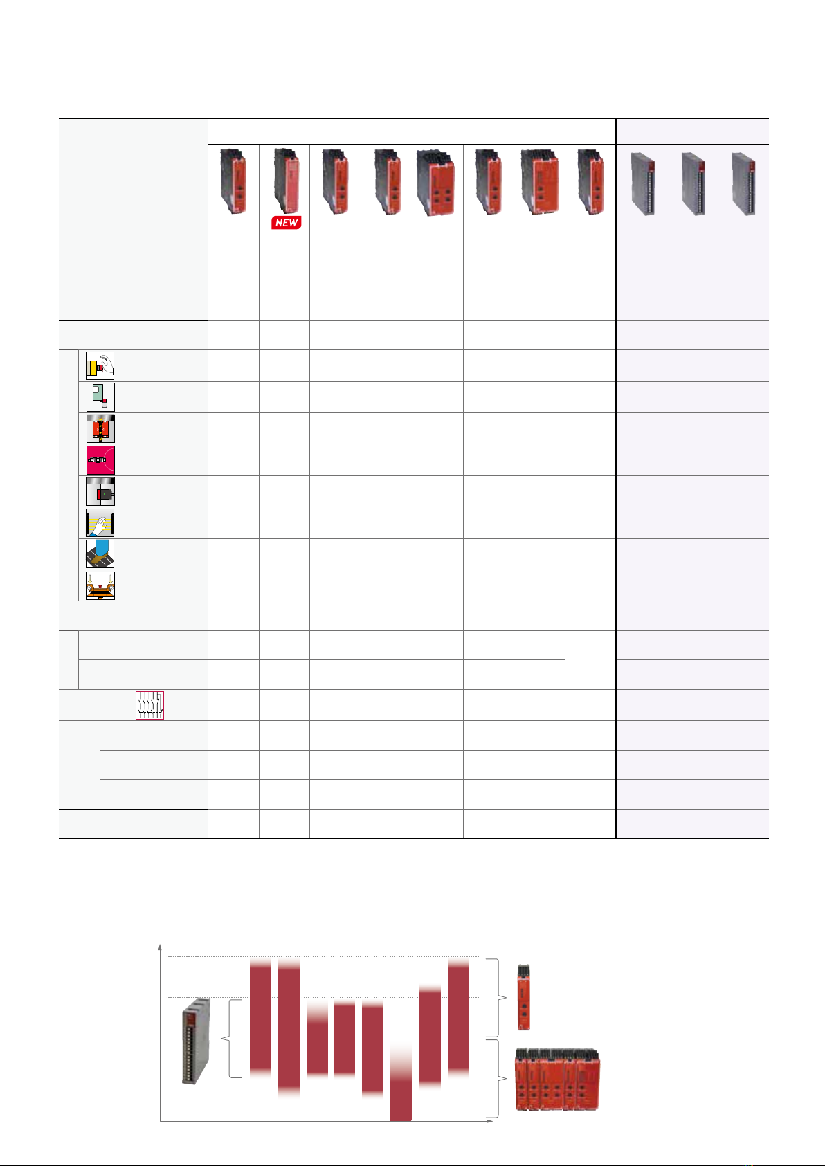
HR6S-ABSafety Relay Module
Data Functional Safety
Dened safe state
Safety-related outputs are
de-energized
Normally Open: open
Normally Closed: closed
Maximum Performance Level (PL), Category
(as per ISO 13849-1:2015) PLc, Category 1
Maximum Safety Integrity Level (SIL)
(as per IEC 61508-1:2010) 1
Safety Integrity Level Claim Limit (SILCL)
(as per IEC 62061:2005+AMD1:2012
+AMD2:2015)
1
Type (as per IEC 61508-2) B
Hardware Fault Tolerance
(HFT) (as per IEC 61508 and IEC 62061) 0
Stop Category for Emergency Stops
(as per ISO 13850 and IEC 60204-1) 0
Lifetime in years at an ambient temperature of 55 °C (131 °F)
20
Safe Failure Fraction (SFF)
(as per IEC 61508 and IEC 62061) >60 %
Probability of Dangerous Failure per hour (PFHD) in 1/h
(as per IEC 61508 and ISO 13849-1) 1175.6 x 10-9
Mean Time To Dangerous Failure (MTTFD) in years
(as per ISO 13849-1) 91 (*1)
Average Diagnostic Coverage (DCavg)
(none as per ISO 13849-1) —
Maximum number of cycles
over lifetime
DC-13 24V DC 2 A: 50000
AC-15 250V AC 3 A: 50000
*1) According to ISO 13849-1 Annex K
• With a variety of common input devices, the HR6S-AB can monitor two-
hand control devices (IIIA) that are required to comply with ISO 13851.
• Suitable for use as a self-holding circuit for selecting a wide variety of
start functions for low-risk machines.
• Output cannot be expanded using expansion modules.
Monitoring of Emergency
Stop circuits as per ISO
13850 and IEC 60204-1,
stop category 0
Monitoring of two-hand
control
devices, type III A
as per ISO 13851
Monitoring of proximity
switches
Monitoring of RFID
sensors
Monitoring of guards as
per ISO 14119/14120
with interlock switches
Monitoring of guards as
per ISO 14119/14120
with coded magnetic
switches
Monitoring of electro-sensitive
protective equipment such as
type 4 light curtains as per
IEC 61496-1
Overview of Application Functions
Safety-Related Outputs
Number of relay contacts, changeover (Normally Closed to
Normally Open), instantaneous 1
Maximum short circuit current IK 1 kA
Maximum continuous current, Normally Open relay contacts 3 A
Maximum continuous current, Normally Closed relay contacts 3 A
Maximum total thermal current ∑ITHERM 3 A
Minimum current 10 mA
Utilization category as per UL 60947-5-1 D300 and R300
Utilization category as per IEC 60947-4-1 and IEC 60947-5-1
AC-1: 250 V
AC-15: 250 V
DC-1: 24 V
DC-13: 24 V
Maximum current, normally open relay contacts
AC-1: 5 A
AC-15: 3 A
DC-1: 5 A
DC-13: 2 A
Maximum current, normally closed relay contacts
AC-1: 3 A
AC-15: 1 A
DC-1: 3 A
DC-13: 1 A
External fusing 6 A, category gG
Additional Non-Safety-Related Outputs
Output voltage 24V DC
Maximum current 20 mA
Terminal Part No. Supply Voltage
Push-in terminal HR6S-AB1C 24V AC/DC
Screw terminal HR6S-AB1P 24V AC/DC
• One sealing strip (see page 28) is included with each product.
HR6S-AB Package Quantity: 1
PLc achieved with Category 1 configuration
Synchronization Times
The synchronization times for the synchronization of safety-related
inputs depend on the application function. (See page 9 Function Mode
Selector and Input Device Connection Example.)
For other specifications (common to all models), see page 27.
• See website for details on
approvals and standards.
S
a
f
e
t
y
A
p
p
r
o
v
e
d
H
R
6
S
*
-
1
4
3
5
.
I
M
.
1
3
5
0
0
5
/
2
0
TÜV NORD Systems
GmbH & Co.KG

9
HR6S Safety Relay Module
Wiring
Function Mode Selector and Input Device Connection Example
K2
K2
M
PLC
S1
L1(+)
12
AC/DC
DC
Power
supply
DC+
Input
CH+ CH+
K1
A1 A2 S11 S12 S13
S2
Start
DC+ CH+
Y1 Y2
B2(*1)
N(-)
14
F1
11
Z1(*1)
Dial 1 Dial 2
Synchronous monitoring: No
Dynamization: Yes
Signal interlock monitoring: No
Synchronous monitoring: 0.5 s
Dynamization: Yes
Signal interlock monitoring: No
Emergency stop switches Interlock switch Two-hand control switch
(IIIA)
DC+ CH+ CH+
S11 S12 S13
Safety fence
DC+ CH+ CH+
S11 S12 S13 DC+ CH+ CH+
S11 S12 S13
S1
S2
Dial 3 Dial 4 Dial 5 Dial 6
Synchronous monitoring: 0.5 s
Dynamization: Yes
Signal interlock monitoring: No
Synchronous monitoring: 2.2 s
Dynamization: Yes
Signal interlock monitoring: No
Synchronous monitoring: No
Dynamization: No
Signal interlock monitoring: No
Synchronous monitoring: 0.5 s
Dynamization: No
Signal interlock monitoring: Yes
Coded magnetic switch (*2)
(1NO, 1NC)
1 PNP output
device
2 OSSD
Output device
DC+ CH+
S11
S1
S12
CH+
S13 DC+ CH+
S11 S12
+-
CH+
S13
PNP
DC+ CH+ CH+
S11 S12
OSSD
0 V
ESPE
24 V
OSSD
S13
*2: Connection examples for coded magnetic switches such as HS7A (IDEC) are also included on the instruction sheet, but certications are not available.
Note: Status of contacts in the diagram: The status of the control switch is when it is not operated. The status of the door interlock is when the door is closed.
HR6S-AB
Designation Explanation
B2 Common reference potential terminal
Z1 Pulsed output for diagnostics, not safety-related
S1 Emergency stop switch
S2 Start switch
K2 Contactor
MMotor
F1 Fuse
*1) For B2 and Z1, see HR6S-AF.

10
• Protects both the operator and the machine by immediately stopping
dangerous movements when instructed to stop by the operator or when a
failure in the safety circuit is detected.
• The most basic module for building a safety system.
Monitoring of Emergency
Stop circuits as per ISO
13850 and IEC 60204-1,
stop category 0
Monitoring of proximity
switches
Monitoring of RFID
sensors
Monitoring of guards as
per ISO 14119/14120
with interlock switches
Monitoring of guards as
per ISO 14119/14120
with coded magnetic
switches
Monitoring of electro-sensitive
protective equipment such as
type 4 light curtains as per IEC
61496-1
Overview of Application Functions
HR6S-AFSafety Relay Module
Data Functional Safety
Dened safe state
Safety-related outputs are
de-energized
open
Maximum Performance Level (PL), Category
(as per ISO 13849-1:2015) PL e, Category 4
Maximum Safety Integrity Level (SIL)
(as per IEC 61508-1:2010) Normally Open: 3
Safety Integrity Level Claim Limit (SILCL)
(as per IEC 62061:2005+AMD1:2012
+AMD2:2015)
Normally Open: 3
Type (as per IEC 61508-2) B
Hardware Fault Tolerance
(HFT) (as per IEC 61508 and IEC 62061) 1
Stop Category for Emergency Stops
(as per ISO 13850 and IEC 60204-1) 0
Lifetime in years at an ambient temperature of 55 °C (131 °F)
20
Safe Failure Fraction (SFF)
(as per IEC 61508 and IEC 62061) <99 %
Probability of Dangerous Failure per hour (PFHD) in 1/h
(as per IEC 61508 and ISO 13849-1) 1.13 x 10⁻⁹
Mean Time To Dangerous Failure (MTTFD) in years
(as per ISO 13849-1) 2,000 (*1)
Average Diagnostic Coverage (DCavg)
(as per ISO 13849-1) ≥99 %
Maximum number of cycles
over lifetime
DC-13 24V DC 1 A: 1,200,000
24V DC 3 A: 180,000
AC-1 250V AC 4 A: 180,000
AC-15 250V AC 1 A: 70,000
250V AC 5 A: 39,000
*1) According to ISO 13849-1 Annex K
Safety-Related Outputs
Number of relay contacts, Normally Open, instantaneous 3
Maximum short circuit current IK 1 kA
Maximum continuous current, Normally Open relay contacts 6 A
Maximum total thermal current ∑ITHERM 12 A
Minimum current 10 mA
Utilization category as per UL 60947-5-1 B300 and R300
Utilization category as per IEC 60947-4-1 and IEC 60947-5-1
AC-1: 250 V
AC-15: 250 V
DC-1: 24 V
DC-13: 24 V
Maximum current, normally open relay contacts
AC-1: 5 A
AC-15: 3 A
DC-1: 5 A
DC-13: 3 A
External fusing 10 A, category gG
Additional Non-Safety-Related Outputs
Output voltage 24V DC
Maximum current 20 mA
Terminal Part No. Supply Voltage
Push-in terminal HR6S-AF1C 24V AC/DC
Screw terminal HR6S-AF1P 24V AC/DC
• One sealing strip (see page 28) is included with each product.
HR6S-AF Package Quantity: 1
Standard module for building safety systems
Synchronization Times
The synchronization times for the synchronization of safety-related
inputs depend on the application function. (See page 11 Function Mode
Selector and Input Device Connection Example.)
For other specifications (common to all models), see page 27.
Output expansion
possible
• See website for details on
approvals and standards.
S
a
f
e
t
y
A
p
p
r
o
v
e
d
H
R
6
S
*
-
1
4
3
5
.
I
M
.
1
3
5
0
0
5
/
2
0
TÜV NORD Systems
GmbH & Co.KG
Other manuals for HR6S Series
1
This manual suits for next models
11
Table of contents
Other IDEC Relay manuals

IDEC
IDEC SmartAXIS FT9Z-1A01 User manual

IDEC
IDEC LD6A Series User manual

IDEC
IDEC HR1S-DMB Series User manual

IDEC
IDEC HR1S-ATE User manual

IDEC
IDEC HR1S-AC User manual

IDEC
IDEC EB3N User manual

IDEC
IDEC SmartRelay FL1A-H12RCE User manual

IDEC
IDEC HR1S-AF 5130B/PB User manual

IDEC
IDEC HR1S-ATE User manual

IDEC
IDEC HR1S-AK User manual


