ICON IP NordicTrack REFLEX 8500 PRO User manual

USER'S MANUAL
CAUT ON
Read all precautions and instruc-
tions in this manual before using
this equipment. Save this manual
for future reference.
Model No. NTL11909.1
Serial No.
Write the serial number in the space
above for reference.
QUEST ONS?
If you have questions, or if parts are
damaged or missing, DO NOT CON-
TACT THE STORE; please contact
Customer Care.
MPORTANT: Please register this
product (see the limited warranty
on the back cover of this manual)
before contacting Customer Care.
CALL TOLL-FREE:
1-800-TO-BE-F T
(1-800-862-3348)
Mon.–Fri. 6 a.m.–6 p.m. MT
Sat. 8 a.m.–4 p.m. MT
ON THE WEB:
www.nordictrackservice.com
www.nordictrack.com
Serial Number ecal

TABLE OF CONTENTS
WARNING ECALPLACEMENT ..............................................................2
IMPORTANTPRECAUTIONS .................................................................3
BEFOREYOUBEGIN .......................................................................5
ASSEMBLY ...............................................................................6
OPERATIONAN A JUSTMENT ............................................................12
HOWTOFOL AN MOVETHETREA MILL ..................................................24
TROUBLESHOOTING ......................................................................26
EXERCISEGUI ELINES ...................................................................29
PARTLIST ...............................................................................30
EXPLO E RAWING .....................................................................32
OR ERINGREPLACEMENTPARTS ..................................................BackCover
LIMITE WARRANTY...............................................................BackCover
NordicTrack is a registered trademark of ICON IP, Inc.
2
This drawing shows the location(s) of the warning
decal(s). f a decal is missing or illegible, call
the telephone number on the front cover of
this manual and request a free replacement
decal. Apply the decal in the location shown.
Note: The decal(s) may not be shown at actual
size.
WARN NG DECAL PLACEMENT

MPORTANT PRECAUT ONS
3
WARN NG: To reduce the risk of serious injury, read all important precautions and in-
structions in this manual and all warnings on your treadmill before using your treadmill. CON as-
sumes no responsibility for personal injury or property damage sustained by or through the use of
this product.
1. Before beginning any exercise program, con-
sult your physician. This is especially impor-
tant for persons over age 35 or persons with
pre-existing health problems.
2. t is the responsibility of the owner to ensure
that all users of this treadmill are adequately
informed of all warnings and precautions.
3. Use the treadmill only as described.
4. Keep the treadmill indoors, away from mois-
ture and dust. Do not put the treadmill in a
garage or covered patio, or near water.
5. Place the treadmill on a level surface, with at
least 8 ft. (2.4 m) of clearance behind it and 2
ft. (0.6 m) on each side. Do not place the
treadmill on any surface that blocks air open-
ings. To protect the floor or carpet from dam-
age, place a mat under the treadmill.
6. Do not operate the treadmill where aerosol
products are used or where oxygen is being
administered.
7. Keep children under age 12 and pets away
from the treadmill at all times.
8. The treadmill should be used only by persons
weighing 350 lbs. (159 kg) or less.
9. Never allow more than one person on the
treadmill at a time.
10. Wear appropriate exercise clothes when
using the treadmill. Do not wear loose clothes
that could become caught in the treadmill.
Athletic support clothes are recommended for
both men and women. Always wear athletic
shoes. Never use the treadmill with bare feet,
wearing only stockings, or in sandals.
11. When connecting the power cord (see page 12),
plug the power cord into a surge suppressor
(not included) and plug the surge suppressor
into a grounded circuit capable of carrying 15
or more amps. No other appliance should be on
the same circuit. Do not use an extension cord.
12. Use only a single-outlet surge suppressor that
meets all of the specifications described on
page 12. To purchase a surge suppressor, see
your local NordicTrack dealer or call the tele-
phone number on the front cover of this man-
ual and order part number 146148, or see your
local electronics store.
13. Failure to use a properly functioning surge
suppressor could result in damage to the con-
trol system of the treadmill. f the control sys-
tem is damaged, the walking belt may slow,
accelerate, or stop unexpectedly, which may
result in a fall and serious injury.
14. Keep the power cord and the surge suppres-
sor away from heated surfaces.
15. Never move the walking belt while the power
is turned off. Do not operate the treadmill if
the power cord or plug is damaged, or if the
treadmill is not working properly. (See
TROUBLESHOOT NG on page 26 if the tread-
mill is not working properly.)
16. Read, understand, and test the emergency
stop procedure before using the treadmill (see
HOW TO TURN ON THE POWER on page 14).
17. Never start the treadmill while you are stand-
ing on the walking belt. Always hold the
handrails while using the treadmill.
18. The treadmill is capable of high speeds.
Adjust the speed in small increments to avoid
sudden jumps in speed.
19. The pulse sensor is not a medical device.
Various factors, including the user's move-
ment, may affect the accuracy of heart rate
readings. The pulse sensor is intended only
as exercise aids in determining heart rate
trends in general.

20. Never leave the treadmill unattended while it
is running. Always remove the key, unplug the
power cord, and press the power switch into
the off position when the treadmill is not in
use. (See the drawing on page 5 for the loca-
tion of the power switch.)
21. Do not attempt to raise, lower, or move the
treadmill until it is properly assembled. (See
ASSEMBLY on page 6, and HOW TO FOLD
AND MOVE THE TREADM LL on page 24.) You
must be able to safely lift 45 lbs. (20 kg) to
raise, lower, or move the treadmill.
22. Do not change the incline of the treadmill by
placing objects under the treadmill.
23. When folding or moving the treadmill, make
sure that the storage latch is holding the
frame securely in the storage position.
24. nspect and properly tighten all parts of the
treadmill regularly.
25. Never insert or drop any object into any
opening on the treadmill.
26. DANGER: Always unplug the power
cord immediately after use, before cleaning
the treadmill, and before performing the main-
tenance and adjustment procedures de-
scribed in this manual. Never remove the
motor hood unless instructed to do so by an
authorized service representative. Servicing
other than the procedures in this manual
should be performed by an authorized service
representative only.
27. The treadmill is intended for in-home use
only. Do not use the treadmill in any commer-
cial, rental, or institutional setting.
28. Over exercising may result in serious injury
or death. f you feel faint or if you experience
pain while exercising, stop immediately and
cool down.
SAVE THESE NSTRUCT ONS
4

Thank you for selecting the revolutionary NordicTrack®
REFLEX 8500 PRO treadmill. The REFLEX 8500 PRO
treadmill offers an impressive selection of features de-
signed to make your workouts at home more enjoyable
and effective. And when youʼre not exercising, the
unique treadmill can be folded up, requiring less than
half the floor space of other treadmills.
For your benefit, read this manual carefully before
using the treadmill. If you have questions after read-
ing this manual, please see the front cover of this man-
ual. To help us assist you, note the product model
number and serial number before contacting us. The
model number and the location of the serial number
decal are shown on the front cover of this manual.
Before reading further, please look at the drawing
below and familiarize yourself with the labeled parts.
BEFORE YOU BEG N
5
Handrail
Console
Fan
Latch Knob Key/Clip
Power Switch
Walking Belt
Foot Pad
Power Cord
Idler Roller
Adjustment Bolts
Accessory Tray
Pulse Sensor

ASSEMBLY
Assembly requires two persons. Set the treadmill in a cleared area and remove all packing materials. Do not
dispose of the packing materials until assembly is completed. Note: The underside of the treadmill walking
belt is coated with high-performance lubricant. uring shipping, some lubricant may be transferred to the top of
the walking belt or the shipping carton. This is normal and does not affect treadmill performance. If there is lubri-
cant on top of the walking belt, simply wipe off the lubricant with a soft cloth and a mild, non-abrasive cleaner.
Assembly requires the included hex key and your own standard screwdriver , Phillips
screwdriver , and wire cutters .
Use the drawings below to identify the assembly hardware. The number in parentheses below each drawing is
the key number of the part, from the PART LIST near the end of this manual. The number after the parentheses
is the quantity needed for assembly. Note: f a part is not in the hardware kit, check to see if it is preattached
to one of the parts to be assembled. To avoid damaging parts, do not use power tools for assembly.
Extra hardware may be included.
6
#8 x 1" Tek Screw
(1)–4
5/16" Star
Washer (4)–4
#8 x 3/4"
Screw (12)–10
1/4" Star
Washer (116)–2
#8 x 1"
Screw (115)–4
#10 x 1/2" Screw
(117)–4
5/16" x 3/4"
Bolt (2)–6
1/4" x 1/2"
Bolt (28)–2 3/8" x 1 3/4" Bolt (3)–2

7
96
1
96
96
96
1
1
1
1
1. With the help of a second person, tip the
Uprights (43) down as shown.
Attach the four Base Feet (96) to the base of the
Uprights (43) with four #8 x 1" Tek Screws (1).
Raise the Uprights (43).
43
2. Identify the Left Handrail (101). Cut the tie from
the Left Handrail. If necessary, press the 5/16"
Cage Nut (99) back into place.
Slide a Handrail Cover (103) onto the lower end
of the Left Handrail (101) as shown. Set the Left
Handrail on the left Upright (43) and slide the
lower end of the Left Handrail onto the bracket
on the left Upright.
Start three 5/16" x 3/4" Bolts (2) with two 5/16"
Star Washers (4) into the left Upright (43) and
the Left Handrail (101). Then, start two #10 x
1/2" Screws (117). Firmly tighten the three
Bolts and the two Screws.
Slide the Handrail Cover (103) against the left
Upright (43).
101
Tie
2
117
4
2
103
43
Bracket
2
99

8
3. Cut the tie from the Right Handrail (102). If nec-
essary, press the 5/16" Cage Nut (99) back into
place.
Cut the tie holding the Upright Wire (93). Route
the Upright Wire through the Right Handrail
(102) as shown.
Slide a Handrail Cover (103) onto the lower end
of the Right Handrail (102) as shown. Set the
Right Handrail on the right Upright (43) and slide
the lower end of the Right Handrail onto the
bracket on the right Upright. Make sure not to
pinch the Upright Wire (93).
Start three 5/16" x 3/4" Bolts (2) with two 5/16"
Star Washers (4) into the right Upright (43) and
the Right Handrail (102). Then, start two #10 x
1/2" Screws (117). Firmly tighten the three
Bolts and the two Screws.
Slide the Handrail Cover (103) against the right
Upright (43).
102
4
2
243
Bracket
117
103
3
Tie
99
93
4. Set the console assembly face-down on a soft
surface to avoid scratching the console assem-
bly. Attach the Left Accessory Tray (110) and
the Right Accessory Tray (111) to the console
assembly with eight #8 x 3/4" Screws (12).
110
12
12
111
12
12
4
Console
Assembly

9
5. With the help of a second person, hold the con-
sole assembly near the Uprights (43). Connect
the Console Ground Wire (55) to the Ground
Wire (105).
Next, connect the console wire to the Upright
Wire (93). See the inset drawing. The connec-
tors should slide together easily and snap
into place. If they do not, turn one connector
and try again. F THE CONNECTORS ARE
NOT CONNECTED PROPERLY, THE CON-
SOLE MAY BE DAMAGED WHEN YOU TURN
ON THE POWER. Then, insert the wires into
the Right Handrail (102) and the right Upright
(43).
Console
Assembly
5
Console
Wire
43
93
93
102
55
105
Console
Wire
6. Set the console assembly on the Left and Right
Handrails (101, 102) and the Uprights (43). Be
careful not to pinch any wires.
Partially tighten two 1/4" x 1/2" Bolts (28) with
two 1/4" Star Washers (116) into the Handrails
(101, 102) and the console assembly. Do not
fully tighten the Bolts yet.
6
102
43
28
101
28
116 116
Console
Assembly
10
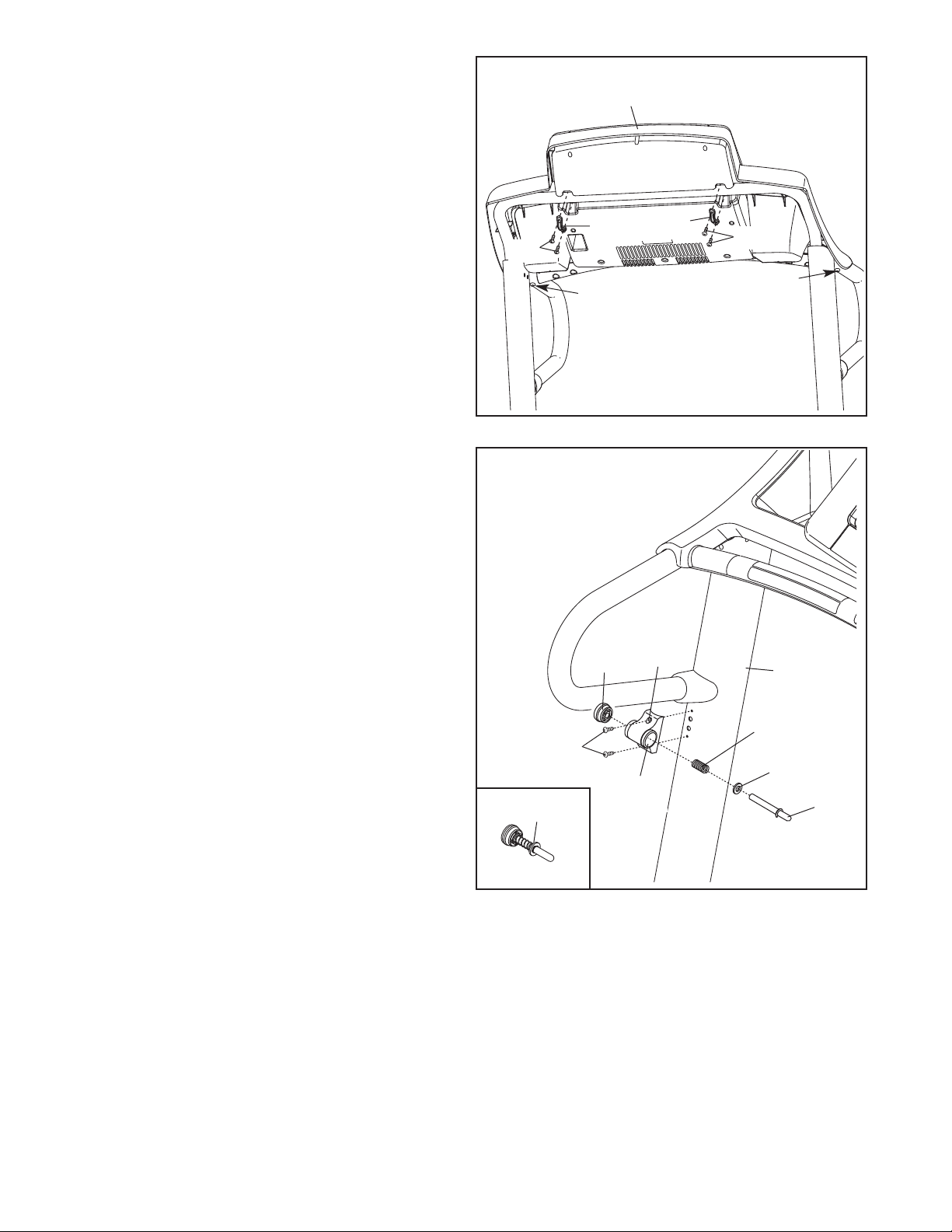
8. Orient the Latch Housing (89) so that the large
hole is on the side shown. Attach the Latch
Housing to the left Upright (43) with two #8 x
3/4" Screws (12). Do not overtighten the
Screws.
Locate the Latch Assembly (88). Remove the
knob from the pin; make sure that the collar and
the spring are on the pin. Then, insert the pin
into the Latch Housing (89), and tighten the
knob back onto the pin.
12
Spring
Knob 89
8
43
Collar
Large
Hole Pin
88
7. Attach the two Console Clamps (104) to the
console assembly with four #8 x 1" Screws
(115). Start all four Screws, and then tighten
all of them. Be careful not to overtighten the
Screws.
Tighten the two 1/4" x 1/2" Bolts (28).
7
104
28 28
115 115
Console
Assembly
104
This manual suits for next models
1
Table of contents
Other ICON IP Treadmill manuals
Popular Treadmill manuals by other brands


Smooth Fitness
Smooth Fitness EVO 3i user manual

NordicTrack
NordicTrack NETL81810.0 user manual

Schwinn
Schwinn 830/Journey 8.0 Assembly manual / owner's manual

Keys Fitness
Keys Fitness HealthTrainer HT-740T owner's manual

Spirit
Spirit XT8 Service manual

NordicTrack
NordicTrack T 14.0 Treadmill Manuel de l'utilisateur