Husky 31313 Assembly instructions

Page-1
All Products limited to Vehicle Tow Rating, see Vehicle Owners Manual. Visit www.huskytow.com for Warranty Information / Tech Support / Product Updates.
2021 Keystone Automotive Operations Inc. All Rights Reserved. 08/05/2021-Rev8
NOTICE
Always drive the king pin into the hitch throat and do not drop the king pin from above into the
hitch head to avoid incorrect hook-ups. Please read Operating Instruction to understand how this
important Safety Feature operates.
Failure to follow all of these instructions may result in death or serious injury
Base Rails Not
Included.
The Husky 16K S 5th Wheel is NOT to be used with rotating pin boxes or pin boxes that require a
“wedge”; such as the REESE Sidewinder, REESE Revolution, 5th Airborne Sidewinder. Use of
these products may damage this product and will void the warranty.
Assembly, Installation, Operation and
Maintenance Instructions
16K S 5th Wheel Hitch
31313 (Hitch Head & Cross Member)
31314 (2 Uprights)
P/N:
31313/31314
90-120 minutes
Dealer / Installer: Provide a copy of these instructions to the end user of this product. These
instructions provide important operating and safety information for proper usage of
this product. Demonstrate the proper use of the product with the end user. Have the
end user demonstrate that they understand the proper use of the product.
End User: Read and follow all instructions included in this manual. Ask your Dealer / Installer for
assistance if you do not understand the proper use of the product. Never remove any
decals from the product. Failure to follow these instructions can result in injury or
death.
WARNING
DO NOT EXCEED Recommended towing limits. SEE VEHICLE’S OWNER’S
MANUAL.
WARNING
WARNING
WARNING

Page-2
All Products limited to Vehicle Tow Rating, see Vehicle Owners Manual. Visit www.huskytow.com for Warranty Information / Tech Support / Product Updates.
2021 Keystone Automotive Operations Inc. All Rights Reserved. 08/05/2021-Rev8
Tools Required
The following tools will be required for installation:
(2) 7/16” wrenches/sockets
(2) ¾” wrenches/sockets
Eye protection
Gloves
Torque wrench capable of 100 ft-lbs. of torque
Package Contents
Box 31313 Contents:
Hitch head (Qty 1)
Hitch Handle w\Grip (Qty 1)
Cross Member (Qty 1)
Hardware kit
Box 31314 Contents:
Uprights (Qty 2)
Introduction
•Safety is of paramount importance in both installation and use of the Husky 16K S
Hitch System. Observe all "Cautions" and "Notes" found in this manual, as well as
common sense precautions to ensure the safety of yourself and others.
•Caution: The Husky 16K S is recommended for use only in truck beds 6 feet or
longer. A Husky EZ Roller combined with a 16K S Hitch is recommended for short
bed truck of less than 8 ft but longer than 6 ft.
•For best results, it is recommended you have your Husky 16K S system (31313
and 31314) professionally installed by a qualified technician.
•The Husky 16K S 5th Wheel Hitch System is designed to tow 5th Wheel Trailers
with a total Gross Vehicle Weight Rating up to 16,000 lbs. do not exceed the rated
capacity.
•King pin weight should never exceed 4,000 lbs.

Page-3
All Products limited to Vehicle Tow Rating, see Vehicle Owners Manual. Visit www.huskytow.com for Warranty Information / Tech Support / Product Updates.
2021 Keystone Automotive Operations Inc. All Rights Reserved. 08/05/2021-Rev8
Prior To Installation
*Check the Truck Payload and Trailer Weight as defined in Appendix A
(Checking Truck & 5th Wheel Trailer Weight Rating). Never Overload
Truck, Trailer or Hitch.
*This Hitch requires Pre-Installed Base Rails which are bolted through the
Bed of the Truck into brackets which in turn are fastened to the Truck
Chassis. DO NOT INSTALL HITCH BY FASTENING TO THE FLOOR OF THE
PICKUP BOX. The Pickup Box Floor is not strong enough to carry the
loads imposed by the trailer
*This 5th Wheel Hitch is rated for a MAXIMUM Pin Weight of 4,000 lbs and a
MAXIMUM Trailer GVW of 16,000 lbs. Exceeding Maximum ratings may
result in death, serious injury or property damage.
The distance from the back of the truck cab to the center of the King Pin (Dim
X) should be 4” greater than one-half the trailer width (Dim Y)
If towing with a short bed truck (less than 8ft but longer than 6ft.) Husky
Towing recommend the use of a Husky EZ Roller for increased turning
clearance at slow maneuvering speeds.
Do not install this 5th Wheel Hitch in a Pickup truck that has a bed shorter
than 6 ft. Towing with this combination of a short bed and 5th Wheel Hitch
could damage the truck and/or trailer. Serious injury or death could occur.
WARNING
WARNING

Page-4
All Products limited to Vehicle Tow Rating, see Vehicle Owners Manual. Visit www.huskytow.com for Warranty Information / Tech Support / Product Updates.
2021 Keystone Automotive Operations Inc. All Rights Reserved. 08/05/2021-Rev8
Assembly & Installation Procedures
1. Hitch Assembly
a) If using pre-existing base rails, ensure that the center to center (fore and aft) distance
is 22” and that there are two pairs of slots in the base rails that are 20 5/8” apart (side
to side). Otherwise contact your local dealer for proper base rail selection and
installation.
b) Place the uprights into the base rails with the decals facing the rear of the truck.
Secure the uprights to the base rails using the ½ inch diameter rail pins and secure
using the large hairclips included in the hardware bag.
c) With the Warning Label of the cross member facing to the driver side of the truck, slide
the cross-member assembly downward over the uprights. Determine the mounting
holes needed to obtain the proper height of the hitch head, and from the inside insert
the four 1/2" diameter bolts into the appropriate cross member mounting holes and
thru each body side. Note: inserting the bolts from the inside will put the lock
nuts on the outside of the cross member, this will ensure that the proper torque
will be applied to the lock nuts.

Page-5
All Products limited to Vehicle Tow Rating, see Vehicle Owners Manual. Visit www.huskytow.com for Warranty Information / Tech Support / Product Updates.
2021 Keystone Automotive Operations Inc. All Rights Reserved. 08/05/2021-Rev8
d) Shims 32043 are provided to adjust crossmember and uprights. Use only if needed
for proper alignment.
e) NOTE: See page 10 for complete height adjusting instructions.
IMPORTANT: The ideal centerline location of the 5thWheel Hitch should be positioned
between 1” and 3” forward of the Center of the Rear Axle once installed in the base rails.
This position may be limited by your specific base rail installation. Always verify this
information before towing down the road and also confirm that you will have adequate
turning clearance between the back of the truck cab and the nose of the 5
th
wheel trailer.
Place shim on either side
as needed
Shim 32043

Page-6
All Products limited to Vehicle Tow Rating, see Vehicle Owners Manual. Visit www.huskytow.com for Warranty Information / Tech Support / Product Updates.
2021 Keystone Automotive Operations Inc. All Rights Reserved. 08/05/2021-Rev8
Hitch Handle Assembly
a. Place the hitch head onto the adjustable cross member and secure with the
supplied 3/8" clevis pins and hair pins. Check for freedom of movement.
b. Rotate the handle shaft while pulling it straight out, once the shaft starts sliding
out of the guide tube pull it all the way out to lock the hitch head in the open
position.
c) Hold the handle with the grip pointed upward and slide the handle onto the
handle shaft.
d) Fasten the hitch handle using the supplied ¼-20 HEX HEAD BOLT and ¼-20
NYLON LOCK NUT. Tighten lock nut until it comes in contact with the tube.
e) Use a wrench to trip the lock mechanism to close the hitch head. Be careful to keep
your body away from any moving parts. The handle should rotate and point down
towards the bed of the pickup truck.
Trip lock mechanism

Page-7
All Products limited to Vehicle Tow Rating, see Vehicle Owners Manual. Visit www.huskytow.com for Warranty Information / Tech Support / Product Updates.
2021 Keystone Automotive Operations Inc. All Rights Reserved. 08/05/2021-Rev8
f) View of final assembly of 16K S 5th Wheel System.
g) Rotate the handle straight up and pull out until it is in the locked open position.
Understanding The Safety Features Of your New HUSKY 5th
Wheel.
The HUSKY 16K S 5th wheel hitch comes standard with a visual aid to indicate what the
current status is of the king pin locking mechanism. Note that the view shown directly
below has a red indicator sleeve on the handle shaft. This is intended to give a quick visual
aid as to whether the hitch head is closed or open. In the two pictures below it is open. The
cross member, uprights and base rails removed for clarity.
RED INDICATOR
SLEEVE
RED INDICATOR
SLEEVE

Page-8
All Products limited to Vehicle Tow Rating, see Vehicle Owners Manual. Visit www.huskytow.com for Warranty Information / Tech Support / Product Updates.
2021 Keystone Automotive Operations Inc. All Rights Reserved. 08/05/2021-Rev8
There is another visual aid that indicates if the hitch head is closed and locked. This is
shown in the picture below with a green shaft that protrudes from the side of the hitch
head. If the king pin has been correctly installed into the mouth of the hitch head the slide
bar will close, the red indicating sleeve will disappear and the green indicator pin will
protrude out as shown below. Cross member, uprights and base rails removed for clarity.
At no time should both the green and red indicator be showing, if this is the case there is
damage to the hitch head and it should not be used. Carefully inspect the hitch for any
damage, also confirm that the handle is installed correctly according to the assembly
instructions in this manual.
Page-9
All Products limited to Vehicle Tow Rating, see Vehicle Owners Manual. Visit www.huskytow.com for Warranty Information / Tech Support / Product Updates.
2021 Keystone Automotive Operations Inc. All Rights Reserved. 08/05/2021-Rev8
Operating Instructions
About Your Husky 16K S
The Husky 16K S 5th Wheel Hitch System is designed to tow 5th Wheel Trailers with a
Gross Vehicle Weight Rating up to 16,000 lbs. Do not exceed the rated capacity as it will
create an unsafe towing condition. It has a 4-way swivel head, its height is adjustable from
14 to 17 inches in one-inch increments and is removed from the bed of the truck by pulling
4 rail pins.
Preparing For First Use
Your Husky 16K S 5th wheel system is now installed and you're anxious to be on your way
down the road. You're almost there but take a few minutes to ensure your hitch is set up
properly for your truck/coach combination by following the steps below.
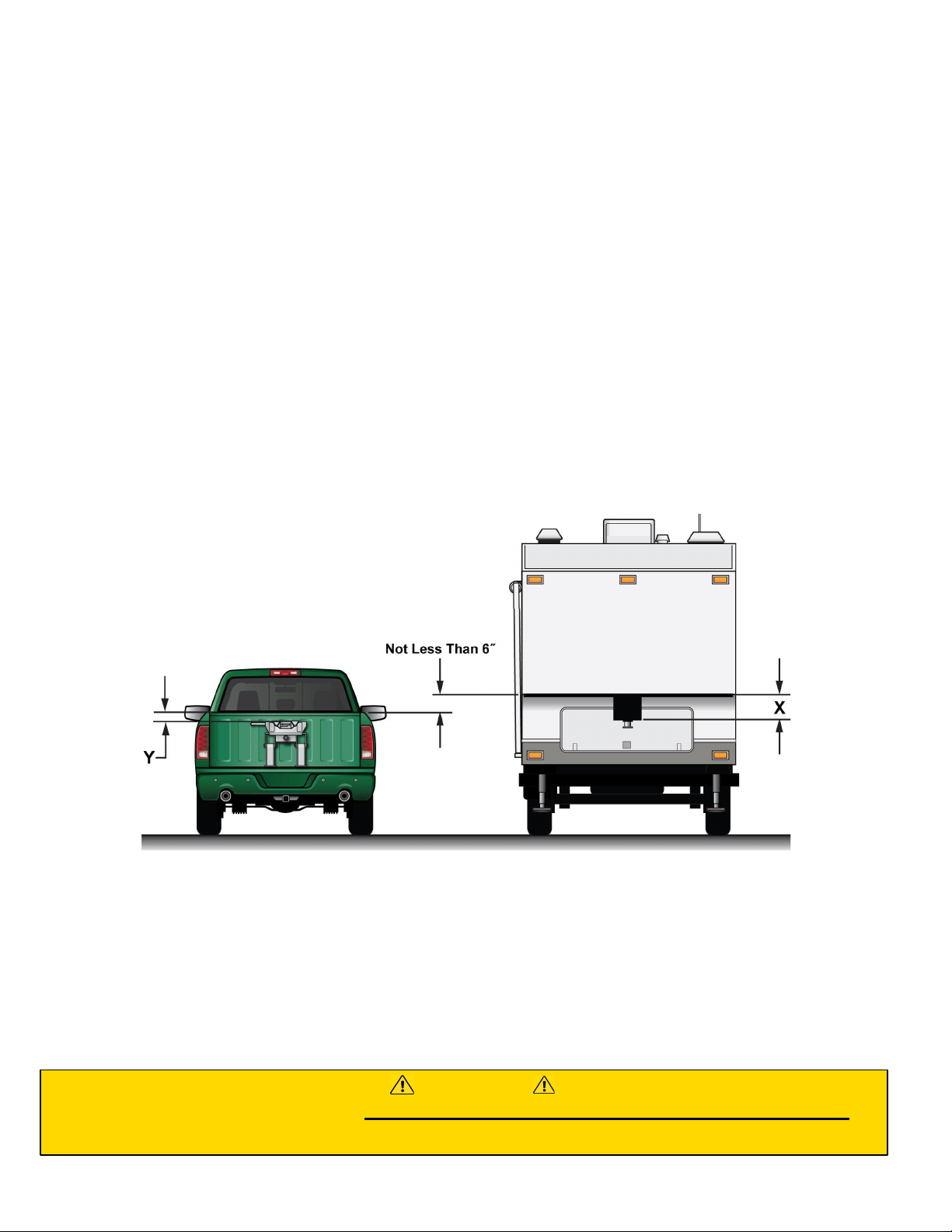
1. Verify that the cross member is set at the proper height to provide a minimum of 6"
clearance between the bottom of the trailer nose and the top of the truck bedsides and
allows for a level-towing attitude of the 5th Wheel Trailer (See Figure 1 below).
Figure 1
With top face of head level measure up to top of pickup box (dimension Y in Figure 1). On
the trailer measure up from the face of the pin box to the underneath of the trailer
(dimension X in Figure 1). Measurement X less measurement Y gives the amount of
clearance between the top of the pickup box and the underneath of the trailer.
At a minimum this should be 6”, if the trailer and tow vehicle are going off-road then this
needs to be 8” to 10”.
If this dimension is less than 6” DO NOT USE THIS TRAILER WITH THIS TOW VEHICLE.
Severe damage may occur to both the pickup box and the trailer.
WARNING

Page-10
All Products limited to Vehicle Tow Rating, see Vehicle Owners Manual. Visit www.huskytow.com for Warranty Information / Tech Support / Product Updates.
2021 Keystone Automotive Operations Inc. All Rights Reserved. 08/05/2021-Rev8
2. If necessary, adjust the cross member to the proper height, ensuring the fasteners are
re-torqued to 75 ft. lbs.
3. Ensure the 5th Wheel Trailer wheels are blocked front & rear & that the rear stabilizer
jacks are fully retracted.
4. Also make sure the 5th Wheel Trailer landing leg feet are on a stable surface.
5. With hitch head level, set trailer king pin box ½” to 1” below hitch so trailer will ride up
and onto hitch. Back Up the truck under the trailer so the king pin enters the hitch.
6. Rotate the handle of the hitch 180 degrees so that the handgrip is pointing straight up
& pull the handle out until the slide bar is held open by the king pin trip mechanism.
The handle shaft has a red indicating sleeve to provide a quick visual reference that
the handle is not closed. You should also note that the green indicator pin is not
protruding from the side of the hitch head.
7. Slowly back the truck so that the bottom plate of the king pin box slides onto the 5th
wheel plate & the king pin slides fully into the throat of the hitch head. Set the parking
brake of the truck & place the transmission into park.
8. Visually verify the slide bar has closed behind the king pin and the king pin box is
resting on the 5th wheel plate. Positively lock the slide bar by rotating the handle
clockwise so the handgrip is pointing straight down at the bed of the truck. The red
indicator sleeve on the handle shaft should not be visible when correctly hitched up
and the green indicator shaft should be protruding from the side of the hitch head.
9. Never back the tow vehicle under the trailer king pin and then lower the king pin into
the hitch. This will result in high pinning and will result in hitch damage and possible
vehicle damage, injury or death!
WARNING
This manual suits for next models
4
Table of contents
Languages:
Other Husky Automobile Accessories manuals


